diy solar

diy solar

Is a precharge resistor needed with a suitable cut off switch?

Red Squirrel

New Member
Joined
Jan 1, 2020
Messages
114
I'm building a portable solar power station, it mostly all works except I have not implemented the cut off switch yet because I was waiting for it to arrive in the mail. I want to be able to turn the entire system off at the battery when not in use otherwise the charge controller will stay on and use power.

I get huge sparks when I do connect the battery manually so it seems the charge controller has a pretty serious capacitor. Inverter does not seem as bad. But normally I am basically connecting both at same time.

Now my question is, once I do add the switch am I ok to have just the switch or should I still have a resistor in parallel with the switch, with it's own switch? Would the switch spark internally damaging the contacts or are they normally designed to actually handle that? Having the resistor was my original intent, but it's proving challenging to physically get this wired up properly and I'm thinking maybe I'm doing all this for nothing and I can just forget it altogether.

This is the switch I went with: https://www.modernoutpost.com/product/blue-sea-6006-m-series-battery-switch/

The system is 12v with a single 79ah AGM battery and 3kw inverter and Renogy charge controller.
 
Hmmm, you should not get big sparks on a 12v system. And AFAIK, charge controllers don't have much (if any) for capacitors. The only time you might get a little spark is if you connect live PV wires to the charge controller in peak sun. In that case, wait till dark or cover the panels for a moment while you connect the wires.

A couple questions. What order are you hooking everything up? You should connect battery to charge controller first, then panels to charge controller. Doesn't really matter when you connect the inverter. Do you have photos of your setup so we can see the wiring? Are you sure you're connecting the wires in the right holes on the charge controller? Which model Renogy controller do you have?
 
Everything is prewired so everything gets hooked up at once, technically. Charge controller and inverter both connected to battery, the switch would then take the battery out of circuit. The solar panels are plugged in the back so are disconnected from circuit when the station is being setup.

On more permanent setups I tend to setup DIN breakers for each item for protection and they can be switched on separately and then just stay on all the time but this is a bit different as the panels will not always be deployed.

I was really surprised too that the charge controller causes that many sparks, but it does appear to have a big capacitor since when I disconnect the battery and no solar panels are connected it will stay on for a while then I will see the battery voltage slowly creep down until it turns itself off.
 
Sorry I'm stumped then. I also have a Renogy 30A controller and it's never created much spark. But perhaps my comment about it not mattering when the inverter is hooked up does matter, I'm not sure. I always connect the inverter second to last, well last before I flip the switch that connects the panels to the charge controller.

For your reference, I'm hooking up 200W panels (12v system) and I've used a 2000W and 1000W inverter. The 1000W creates as big of a spark as the 2000W, but it's higher quality (Victron vs Renogy), so perhaps the caps are bigger or equal in size. If I hook the panels in full sun, I do get some spark, but not as big as the inverter spark. I've never tried nor seen anyone mention using a pre-charge resistor for hooking up panels to a charge controller. So I don't know if what you're experience is abnormal or not.

edit: just saw you have a 3000W inverter but only a 79Ah battery. Not a good idea, regardless of whether the battery is lead-acid or lithium. That inverter can pull about 300A and a 79Ah lead acid battery is going to experience MAJOR voltage drop if you try to run the inverter at the full 3000W. No idea if that has anything to do with your sparking on the controller, but thought I should mention that
 
I won't be typically loading it up to it's full capacity, I just like the ability to be able to momentarily (ex: mitre saw) if I need. I did 1800w as a test and yeah the voltage drop is massive and I also lose capacity much faster. Typically though I'll be pulling 400w or so, maybe 800w. It will mostly be to charge my chainsaw batteries, Ryobi batteries and powering other similar loads. Though I might also power my air compressor with it, which might perhaps be a bit much. I tested and it works, but it's probably hard on the battery to pull that much from it. Once I build a storage shed I will probably also add a larger solar setup inside of it so I can power the big loads. Ideally I want to go 48v with 8 golf cart batteries for my next one. I only went AGM for this for portability reasons and lithium drop-in replacements are way more money than I want to spend.
 
I won't be typically loading it up to it's full capacity, I just like the ability to be able to momentarily (ex: mitre saw) if I need. I did 1800w as a test and yeah the voltage drop is massive and I also lose capacity much faster. Typically though I'll be pulling 400w or so, maybe 800w. It will mostly be to charge my chainsaw batteries, Ryobi batteries and powering other similar loads. Though I might also power my air compressor with it, which might perhaps be a bit much. I tested and it works, but it's probably hard on the battery to pull that much from it. Once I build a storage shed I will probably also add a larger solar setup inside of it so I can power the big loads. Ideally I want to go 48v with 8 golf cart batteries for my next one. I only went AGM for this for portability reasons and lithium drop-in replacements are way more money than I want to spend.

That's the problem with a setup like that. "I won't use it to full capacity and I'll keep an eye on it". Those are famous last words. Way too easy to run more off the battery than you think you are, simply because the inverter can do it.

I don't recall if I've seen a chart that helps you determine AGM battery size Ah and voltage drop based upon amp draw. Meaning, I'm not sure if your 79Ah battery will last you 30 cycles or 300 at the abuse you are likely putting it through. I understand that lithium batteries are more expensive, but you can occasionally find a CHINS or the like on crazy good sales for $200-250 for 100Ah. Which is only a 100A BMS and won't power a 3000W inverter more than about 1000W but it won't have near the voltage drop issue either. But two in parallel would give you 200A or approx 2200W.

We spent over $1000 on AGM batteries and it was an expensive lesson. Had no idea about their voltage drop issues and they are finicky to charge. Finally switched to LiFePO4 and holy cow, what a difference. Voltage barely drops and it's super easy to charge, full sun, clouds, 5-10A shore charger, whatever it eats it all up. No long absorption time like lead acid and AGM in particular needs at least a weekly high C-rate of charge (we needed 40-60A on our 200Ah AGM bank, which makes for an expensive charger on dying/broken batteries. As you can see, I'm bitter about using AGM. Granted these were cheapo Renogy batteries not the quality ones like Trojan or Odyssey. I assume most AGM are junk like the Renogy ones unless one of the famous $$$ brands. All stuff I didn't know when we bought the Renogy ones but have learned through this forum and wish we had saved a ton of money and gone with lithium at the beginning. We now have 2x the battery bank of lithium (200Ah lithium which you can safely use 90% DoD vs 200Ah AGM of which only 100Ah is usable due to 50% DoD unless you go with said $$$ expensive name brand AGM) for less money than we paid for the AGM batteries (we went through 4x 100Ah AGM due to killing them with our inexperience of not charging them properly).
 
Oh yeah I get that, I'm also limited by 200w nameplate solar as that's what the portable panel is, but I rather have more inverter capacity than I need than not enough, so it can deal with surge loads etc. Lithium cells are very hard to get here and I'm not that great at electronics yet to design the balance charging circuitry (eventually do want to look into that) and the AIO batteries that can be treated like lead acid are also VERY expensive, like over a grand. Although the AGM was not that cheap either, about $300ish. For stationary systems I usually do golf cart batteries, they are way cheaper per watt hour, and I also tend to have more. This system is just so I have power until I can build a structure on my off grid land. It may also be used to power a pump when I go get water at the lake, but I might have to revisit that because it's HEAVY. Going to be very hard to load and unload in the truck and I only want to have to do that once. I may end up just building a solar trailer that also has room for the water tank.
 
but I rather have more inverter capacity than I need than not enough, so it can deal with surge loads etc

That's the thinking of many who buy an inverter bigger than their needs. It really can help to measure what your actual needs are. The paper version is to add up the numbers based upon specs of the devices, the real version is to use meters to measure actual amps, including the intial in-rush surge for things like pump motors or compressors.

Do you know the actual power needs of the devices you wish to power from the inverter? And do you a have a clamp amp meter that can handle the amps you think you will be measuring? You want a clamp meter than can measure in-rush current, which will show you what your true surge load is. Usually the surge happens for less than a second and whether or not your inverter can handle it depends not only on the size of the inverter but the quality of it's build. My 1000W Victron can handle surge better than my 2000W Renogy, for the size.

I have read many times that an inverter much larger than 2000-2200W on a 12v system is hard to do and you're better off going to a 24v or 48v system. The wires needed become very large at that point and the amp draw on the battery (and resulting voltage drop) is rough unless you have a very large lead acid bank.
 
I know the loads are under 1800w as they are rated for a standard outlet. Of course the surge can be more, but most non chinesium inverters can handle double that. Basically this is a 200w system with 2,000w+ surge, if I was to actually rate it. I have not actually measured the loads, only test run them. This is going to be general purpose so it won't be limited to a single number of loads. Basically the idea is to use it to power whatever 120v item I need to power, with of course taking into account that I only have 200w coming in.

But back to my original question, should I go ahead with the resistor switch setup or just wire the big switch in directly? Are these type of switches designed to actually handle the sparking? It would not be switched under load but there is still going to be sparks from initial connection.
 
But back to my original question, should I go ahead with the resistor switch setup or just wire the big switch in directly? Are these type of switches designed to actually handle the sparking? It would not be switched under load but there is still going to be sparks from initial connection.

I'm not sure as I don't understand why you're getting such a large spark with only 200W input. Something doesn't sound right there. The spark from connecting your 3000W inverter should be much larger (if you don't use a pre-charge resistor).

Personally, on one hand, if the system is working, I wouldn't worry about it since you won't be using the switch under load, but not knowing why there's such a large spark on the SCC upon initial contact concerns me. Is it a single 200W panel or multiple wired together? If single, what is the VOC and if multiple, are they wired in series or parallel or a combo and what is the VOC of each panel?

If you have 2x100W panels wired in series, that's going to give you a VOC of around 40-44V. Maybe that would give a bigger spark as I've only dealt with 100W panels wired in series so the VOC is about 21V.
 
The panels are out of the equation when I connect it, it's just the charge controller alone, as the battery does power it to show the display etc. It seems they decided to put a fairly beefy capacitor in there on the battery side. I might go ahead and just add the resistor anyway to be safe. I was also adding a switch for the fan so it's all wired in to the same box anyway.
 
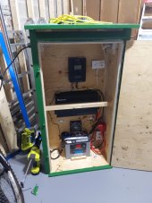
So wiring is done, did end up going with resistor, I feel better doing it that way than wondering if the switch is being damaged every time I use it. This is more or less the final product. The solar panels stow away in front and door closes over them.

The two small switches at the bottom right on the white plate are the resistor, and fan switch. Then the main switch is on the side, in red. Basically to turn on I turn on the small switch first, wait for battery voltage display on charge controller to go to 12v or whatever the battery voltage is at, then I turn on the main switch, and optionally the fan, which is the other small switch.

Other pic was from some initial testing when I was manually connecting battery.

IMG_20230705_003153.jpg
 

Attachments

  • IMG_20230622_192540.jpg
    IMG_20230622_192540.jpg
    323.7 KB · Views: 6
Nice package. FYI: there is a 3 position main switch you could use to reduce user error (position 1 has resistor, and position 2 is battery without resistor).
 
That is a good idea, if I could find a place to buy something like that here in Canada. I'd have to dig around some more next time.
 
Back
Top