bradley.r.zeller
New Member
Hi all!
First post and I must start out by expressing my gratitude for this community. I’ve learned a ton in the past several weeks. Thanks!
I would love some help in designing a system for my situation. Any and all advice or comments are much appreciated!
Here’s my situation and what I’m trying to accomplish…
I have an old 3.3 kW system on my south facing roof that was installed by the previous home owner in 2009. I ran some calculations and believe they are performing at around 82%, producing around 2.7kW. I live in Southern California and get good sun year round. I’m grandfathered in to NEM 1.0 but it doesn’t really matter since my home consumes almost 100% of what my system produces (it occasionally back feeds when we’re not home during the day but negligible amounts). I believe my system offsets close to half of my energy consumption. However, I have no batteries and no resilience to power outages.
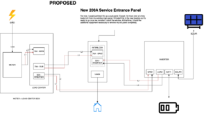
My end goal is to reduce my grid consumption / reliance down to zero (saving money) and to have uninterruptible power to my home at all times, even in a grid outage. I’d like to replace my entire existing system with a new one to accomplish these goals.
Now, I am obviously constrained by a budget so I’m trying to figure out how to iteratively build towards my end goal.
I’m feeling fairly certain that this initial investment will be for the powerpro battery, 18k pv and 14 x 380W panels.
Down the road, as I can afford, I’d like to be able to add batteries and panels if needed. But I feel good about the initial equipment getting me a solid way towards my goals.
Now, my questions!
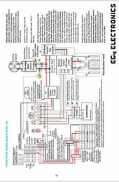
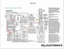
1. The 18k manual shows a wiring diagram (4.4, attached below) for whole house backup configuration. I’m thinking this is what makes most sense for me. Since I have no interest in back-feeding the grid, would my wiring configuration be any different or the same?
2. I have an old 100A main load center + meter combo box. Do y'all think it will be possible to insert the necessary equipment (feeder tap + breaker) between the two? I was hoping I could potentially add this equipment in the attic above the panel instead of opening my exterior wall… and does it even make sense to add the feeder tap and breaker in the attic? Or do they need to be accessible? Or do you think I’m going to need a new panel with a new (separate) meter?
3. What is the PV interactive system 2 pole fused disconnect? And do I need this if I’m not exporting to grid?
4. I’m planning on using my existing roof rail to mount the new panels. Any concerns there or are these racking rails pretty universal?
5. Permitting - I’m a bit surprised I don’t see this topic talked about much on the community. I know it varies so much by location but I was wondering if a system like this typically requires permits or not. Again, I’m not exporting to the grid so maybe that plays a role in whether or not I need to get permits. I’d honestly prefer to get this system permitted for the sake of checking my work but it’s an intimidating path to go down because of the extra money and slowness of the whole process. Any guidance here?
6. I did talk to building and safety in my city and they told me that I’d need a single line diagram showing my system. Do you think the manual’s diagram below would suffice as that diagram? I could modify to remove a few things that are irrelevant but for the most part, that seems like it could work.
7. I’m also considering the 6000XP due to its affordability. I don’t believe the 6000W output would be too much of an issue in my case and I believe this system will switch to grid in the case the load exceeds 6000W, right? I also don’t think the 8kW solar input is a limitation in my case. However it does seem like the 18k has more features that would be helpful for accomplishing my goals… or are these two inverters more similar in features than I think?
8. I see in the diagrams that the ct sensors need to go as close to the meter as possible. However, in some of Will’s videos, he has the ct sensors in the inverter wiring bay on the AC in wires… that seems much simpler than getting them into the meter box. Will this work? Or why do they need to be close to the meter?
9. Any other advice for my situation?!
Thank you community!
First post and I must start out by expressing my gratitude for this community. I’ve learned a ton in the past several weeks. Thanks!
I would love some help in designing a system for my situation. Any and all advice or comments are much appreciated!
Here’s my situation and what I’m trying to accomplish…
I have an old 3.3 kW system on my south facing roof that was installed by the previous home owner in 2009. I ran some calculations and believe they are performing at around 82%, producing around 2.7kW. I live in Southern California and get good sun year round. I’m grandfathered in to NEM 1.0 but it doesn’t really matter since my home consumes almost 100% of what my system produces (it occasionally back feeds when we’re not home during the day but negligible amounts). I believe my system offsets close to half of my energy consumption. However, I have no batteries and no resilience to power outages.
My end goal is to reduce my grid consumption / reliance down to zero (saving money) and to have uninterruptible power to my home at all times, even in a grid outage. I’d like to replace my entire existing system with a new one to accomplish these goals.
Now, I am obviously constrained by a budget so I’m trying to figure out how to iteratively build towards my end goal.
I’m feeling fairly certain that this initial investment will be for the powerpro battery, 18k pv and 14 x 380W panels.
Down the road, as I can afford, I’d like to be able to add batteries and panels if needed. But I feel good about the initial equipment getting me a solid way towards my goals.
Now, my questions!
1. The 18k manual shows a wiring diagram (4.4, attached below) for whole house backup configuration. I’m thinking this is what makes most sense for me. Since I have no interest in back-feeding the grid, would my wiring configuration be any different or the same?
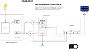
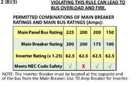
2. I have an old 100A main load center + meter combo box. Do y'all think it will be possible to insert the necessary equipment (feeder tap + breaker) between the two? I was hoping I could potentially add this equipment in the attic above the panel instead of opening my exterior wall… and does it even make sense to add the feeder tap and breaker in the attic? Or do they need to be accessible? Or do you think I’m going to need a new panel with a new (separate) meter?
3. What is the PV interactive system 2 pole fused disconnect? And do I need this if I’m not exporting to grid?
4. I’m planning on using my existing roof rail to mount the new panels. Any concerns there or are these racking rails pretty universal?
5. Permitting - I’m a bit surprised I don’t see this topic talked about much on the community. I know it varies so much by location but I was wondering if a system like this typically requires permits or not. Again, I’m not exporting to the grid so maybe that plays a role in whether or not I need to get permits. I’d honestly prefer to get this system permitted for the sake of checking my work but it’s an intimidating path to go down because of the extra money and slowness of the whole process. Any guidance here?
6. I did talk to building and safety in my city and they told me that I’d need a single line diagram showing my system. Do you think the manual’s diagram below would suffice as that diagram? I could modify to remove a few things that are irrelevant but for the most part, that seems like it could work.
7. I’m also considering the 6000XP due to its affordability. I don’t believe the 6000W output would be too much of an issue in my case and I believe this system will switch to grid in the case the load exceeds 6000W, right? I also don’t think the 8kW solar input is a limitation in my case. However it does seem like the 18k has more features that would be helpful for accomplishing my goals… or are these two inverters more similar in features than I think?
8. I see in the diagrams that the ct sensors need to go as close to the meter as possible. However, in some of Will’s videos, he has the ct sensors in the inverter wiring bay on the AC in wires… that seems much simpler than getting them into the meter box. Will this work? Or why do they need to be close to the meter?
9. Any other advice for my situation?!
Thank you community!
Attachments
Last edited:
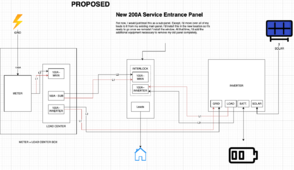
 Is that a terrible idea? haha.That would allow me to make the inverter breaker on my MSP 50A (see diagram below).