diy solar

diy solar

Neutral to/from Critical Loads Panel Question

MisterSandals

Participation Medalist
Joined
Nov 5, 2019
Messages
10,093
Location
Silicon Valley
I am in the process of installing a Schneider SW4048 with MidNite Solar E-panel in-between my main panel and an existing sub panel (my new critical loads panel).

Its pretty clear that i need to route L1 and L2 from main to SW4048. Return from SW4048 will connect to L1 and L2 in the sub panel.

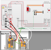
I am intending to leave neutral to sub panel as is, connected centrally spaced (meaningful?) between L1 and L2. I need to run neutral to the SW4048. My question: Is it important that this neutral connect to the neutral in a centrally spaced location or can it attach anywhere on the side neutral bar in the sub panel (as pictured in the diagram and circled in the pic)?

I would REALLY appreciate any feedback on how i intend to wire the AC side. All the wires will be 8AWG THHN 90C copper. Longest wire will be less than 3ft. All AC amps will all be less than 50A.
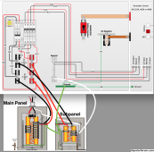
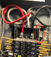
Schneider-Main-Sun.png


Screen Shot 2023-11-27 at 3.00.32 PM.png
 
Why have the neutral and ground direct to subpanel vs from the E-Panel? I know you said existing but wouldn’t that do some weird loop? Maybe it doesn’t matter, imagine if you had the inverter connected via an interlock to subpanel.

Sorry I know i didn’t answer your question.
 
Last edited:
I am in the process of installing a Schneider SW4048 with MidNite Solar E-panel in-between my main panel and an existing sub panel (my new critical loads panel).

Its pretty clear that i need to route L1 and L2 from main to SW4048. Return from SW4048 will connect to L1 and L2 in the sub panel.

I am intending to leave neutral to sub panel as is, connected centrally spaced (meaningful?) between L1 and L2. I need to run neutral to the SW4048. My question: Is it important that this neutral connect to the neutral in a centrally spaced location or can it attach anywhere on the side neutral bar in the sub panel (as pictured in the diagram and circled in the pic)?

I would REALLY appreciate any feedback on how i intend to wire the AC side. All the wires will be 8AWG THHN 90C copper. Longest wire will be less than 3ft. All AC amps will all be less than 50A.


View attachment 179986


View attachment 179988
Only important neutral issue is with gfci breakers.
Ok to connect anywhere on the neutral bar.
 
I know you said existing but wouldn’t that do some weird loop? Maybe it doesn’t matter, imagine if you had the inverter connected via an interlock to subpanel.
There is an interlock (upper left 3 2-pole breakers in E-panel) but that only involves L1 and L2.

Only important neutral issue is with gfci breakers.
Ok to connect anywjere on the neutral bar.
Great, thanks!
 
I favor having neutral wire adjacent to L1/L2, such that imbalanced 120V current flow has a loop with approximately zero area.

In my case, with inverters hanging off a Tee conduit, I ran a single neutral (and a single ground) to the inverters. In particular due to conduit fill problems.

If the inverters had been in-line with separate input and output conduit, I would have run neutral and ground in one conduit, connect to inverter, out the other conduit.

In your case, if you daisy chain the two panels, I think you could daisy chain the neutral and ground.

Except, if main panel can be fed by the grid and sub-panel fed by the inverter, neutral (and maybe ground) would have to handle the sum of both currents. And I'm not sure it would be Kosher to have inverter making use of a neutral that is shared with grid. At the very least, whatever IR drop you generate in neutral would show up as backfeed on L1/L2 in a grid down situation.

[Edit: I misread the diagram. No problem with shared neutral. https://diysolarforum.com/threads/neutral-to-from-critical-loads-panel-question.73476/post-933528 ]
 
Last edited:
I favor having neutral wire adjacent to L1/L2, such that imbalanced 120V current flow has a loop with approximately zero area.

In my case, with inverters hanging off a Tee conduit, I ran a single neutral (and a single ground) to the inverters. In particular due to conduit fill problems.

If the inverters had been in-line with separate input and output conduit, I would have run neutral and ground in one conduit, connect to inverter, out the other conduit.

In your case, if you daisy chain the two panels, I think you could daisy chain the neutral and ground.

Except, if main panel can be fed by the grid and sub-panel fed by the inverter, neutral (and maybe ground) would have to handle the sum of both currents. And I'm not sure it would be Kosher to have inverter making use of a neutral that is shared with grid. At the very least, whatever IR drop you generate in neutral would show up as backfeed on L1/L2 in a grid down situation.
Im not sure i understand.

How could Neutral from an inverter feed anything to the grid?

Neutral is for unbalanced 120V loads to source.
If grid isnt supplying, then it isnt the source.
 
My XW is in this neutral config and it works fine for me, in grid passthrough and off grid output.

Mine is backfed into the subpanel via a breaker not the main lugs, so that I can always bypass back to plain grid. So yes it feeds into one of the neutral sides. I don't think there's a lot of importance there unless you were getting over 100A then I'd want it up on the fatter neutral bus.

Homeline has 70A and 100A neutral lugs you can add to the side bar that might feel better for the 8 awg.

Ideally I'd get the main breaker kit for the subpanel, so that an interlock can be installed to switch it between regular grid feed and the breaker backfeed from inverter. But you already have bypass in your e panel anyway.
 
Last edited:
If main panel has L1/N/L2 to grid, and sub panel has L1/N/L2 to inverter,
consider grid down. Consider a length of N shared by both circuits.
If inverter feeds a 120V 10A load, 10A in N causes voltage offset.
A 120V load on main panel connect shared N to L1.
Some voltage appears on L1 of "down" grid.

If N became open, full 120V would appear on L1 of "down" grid.

This is similar to the situation of "objectionable current", where if a load uses ground as part of its return path, some voltage would appear on ground of other circuits.

In a performance review, I was once accused of dwelling on off-normal cases.
I consider that my job as an engineer.
Yowsa.
I suppose there could be something a scope could pick up.
My training says nothing would be there.
 
Aha! I see your reasoning.
Sure, if open N from grid occured, any imbalance would search all paths... even through earth to the pole.

OP. if things act wacky, shut down and look for a bad N from grid!
 
If N became open, full 120V would appear on L1 of "down" grid.
I think I'd need a picture to get this one. My gut tells me you might find the neutral getting bent 3v one way or another in the closed neutral scenarios but open neutral I don't get it at all, there's no more connection between the sub and main except for the ground.

Anyway I don't consider open neutral faults in my design because they're too scary so I'll just crawl back in my hole.
 
Yes, a couple volts at max current. Assuming solid connection of neutral.
Consider this similar to multi-wire branch circuit, but with two different sources.

I would really recommend NOT using a single neutral wire to complete the circuit from two different panels, unless they are daisy chained with main panel feeding L1 and L2 of sub panel.

If a single neutral wire could carry return current of one circuit on grid and return current for another circuit on inverter, I would say give them separate neutral wires. OK for the neutral of grid circuit to provide neutral-ground bond of inverter (for fault current which will trip a breaker), but not to complete the circuit of inverter.
 
If a single neutral wire could carry return current of one circuit on grid and return current for another circuit on inverter, I would say give them separate neutral wires.
I'm still not quite getting how they would share a wire path here. And whether they do or don't whats the difference between 2 and one of the all the neutrals are bonded all the time in the end? Redundancy.

It does kind of make my head hurt to imagine the grid and inverter's unsynchronized waveforms both acting on the neutral, but I just reassure myself, with shaking confidence, that power can only return to it's source and they're two separate sources.
 
1701138472316.png

Assuming grid feeds main panel, and inverter feeds sub panel (I'm not clear on the switching), assume inverter is disconnected from the grid.
There is a neutral wire from main panel to sub panel back to something in that switch box.
Inverter drives a 120V load in sub panel, with its current returning in neutral wire to that switch box.
Grid drives a 120V load in main panel, with its current returning in neutral wire to sub panel, then in neutral wire from sub panel to that switch box.
Return current from inverter's load and from grid load add together in that last section of neutral wire. Add as vectors, depending on phase.

I'm still not quite getting how they would share a wire path here. And whether they do or don't whats the difference between 2 and one of the all the neutrals are bonded all the time in the end? Redundancy.

If the two were in parallel, I wouldn't worry (much). If one was skinnier and shorter than the other, it might carry too much current.
But these are in series, so no redundant path. The only way for current to get back is to share the neutral wire from sub panel to switch box thing.
 
Grid drives a 120V load in main panel, with its current returning in neutral wire to sub panel, then in neutral wire from sub panel to that switch box.
This is where I'm stuck. Why would a grid neutral load in main panel be going towards the sub panel, wouldn't it just be heading back up the grid feeder?

I am clearer now on the point though, about MWBC style neutral current sharing risks.
 
Look at the diagram posted above, with red/black wires from main panel going one place, but white wire going to sub panel. That's why neutral current from 120V load on main panel would flow through neutral of sub panel. So I wouldn't want it wired that way.
 
Mmm, no I'm still stuck. Are you getting that the E Panel is in bypass or inverter mode but not both? You can leave me stuck though.
 
Zooming in to where I can read "AC input" and "AC output", also "Main Panel L2 L2 N", I think I'm wrong.
I had thought both Main Panel and Sub Panel were fed by that switchbox thing.
Now I see Switchbox Thing is fed by Main Panel, and Sub Panel is fed by Switchbox Thing.
(no top-down or left-right flow in the diagram, and I didn't pay attention to the details.)

I no longer think there is a problem with it.
Carry on.
 
Back
Top