You are using an out of date browser. It may not display this or other websites correctly.
You should upgrade or use an alternative browser.
You should upgrade or use an alternative browser.
Please check wiring multiplus-II 24v
- Thread starter gr8pix
- Start date
sunshine_eggo
Happy Breffast!
EDIT: Yeah, per @pvgirl, there are some wiring/fuse mismatches. I didn't consider the inverter + DC load potential, and I just missed the 250A on the 4awg wire.
90°C rated 1/0 is falls just short of the 179A total draw of both at max draw.
Just want to make sure you know the VE.Bus smart dongle is primarily for monitoring only. Can't be used to configure inverter.
The only control it permits via VC is setting inverter to ON/OFF/Charger only and changing the AC input current limit.
Last edited:
I'd recommend larger wire between the battery and the inverter such as 2/0, 4/0 would be preferred. 250amp fuse is much to large for the DC-DC converters, consider separate 70 amp fuses for each converter with individual 6 or 4 awg runs to the converters depending on distance. Depending on distance between the converters and the DC loads/fuse panel consider upping that wire to 1 or 1/0 AWG.
gr8pix
New Member
Thank you for looking at it, I've been reading a lot of your posts! I'll be picking up a USB adapter as well as either a Cerbo GX, or Venus OS to do all the other fancy stuff that these systems are capable ofNot seeing any concerns. Just want to make sure you know the VE.Bus smart dongle is primarily for monitoring only. Can't be used to configure inverter.
The only control it permits via VC is setting inverter to ON/OFF/Charger only and changing the AC input current limit.
sunshine_eggo
Happy Breffast!
Thank you for looking at it, I've been reading a lot of your posts! I'll be picking up a USB adapter as well as either a Cerbo GX, or Venus OS to do all the other fancy stuff that these systems are capable of
Sometimes I'm not worth listening to. See my edited post and listen to @pvgirl
If you go RPi, make sure it makes $ sense buying the proper adapters. You'll need MK3-USB to connect the RPi. Not certain, but I think the Orions get left out of the VRM ecosystem.
gr8pix
New Member
I think you're right about the Orions, they have to be manually adjusted see here https://diysolarforum.com/threads/victron-24-12-70-in-parallel-for-leveling-jacks.24345/post-874980. I'm trying to put this together as cost effective as possible so I may just bite the bullet and go with the Cerbo GX and touch screen as I can wire my tank sensors, gen start etc. I'll decide once I get this phase done , it's hardest part of the install.Sometimes I'm not worth listening to. See my edited post and listen to @pvgirl
If you go RPi, make sure it makes $ sense buying the proper adapters. You'll need MK3-USB to connect the RPi. Not certain, but I think the Orions get left out of the VRM ecosystem.
gr8pix
New Member
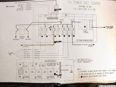
Thank you, I will revise the battery wiring and repost. The DC load will be huge, 150A DC for the Gen start, and Slides together. I wont be running them all at the same time hopefully it will work. I'll revise and run separate line from the Lynx with 70A fuses on each then wire the output parallel to the DC loads using 1/0. Here is my 12V distribution.I'd recommend larger wire between the battery and the inverter such as 2/0, 4/0 would be preferred. 250amp fuse is much to large for the DC-DC converters, consider separate 70 amp fuses for each converter with individual 6 or 4 awg runs to the converters depending on distance. Depending on distance between the converters and the DC loads/fuse panel consider upping that wire to 1 or 1/0 AWG.

gr8pix
New Member
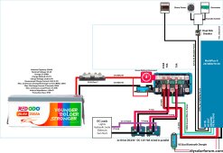
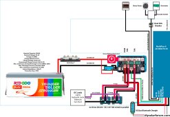
I'd recommend larger wire between the battery and the inverter such as 2/0, 4/0 would be preferred. 250amp fuse is much to large for the DC-DC converters, consider separate 70 amp fuses for each converter with individual 6 or 4 awg runs to the converters depending on distance. Depending on distance between the converters and the DC loads/fuse panel consider upping that wire to 1 or 1/0 AWG.
 I hope I did this correctly!?
gr8pix
New Member
With Black Friday specials out there now I may want to add another battery 200AH in parallel. The only wires that I'd need to up-size would be the wire from the Battery to the Lynx Distributor and from the Lynx to the Multiplus II to 4/0 Another Class T 225A and holder would be needed for the second battery, as well as a mega fuse for the Lynx Distributor, the highest they go is 400A, How do I deal with this?
gr8pix
New Member
Less than 3 ft to the Lynxhow long are your inverter wires?
Thanks for sharing this. Is if fair to assume you revised (ninja edit) the wire diagram on your first post to accommodate the suggestions? Second... what is your plan for keeping your rig running right if you blow one of the 70 amp fuses in the Lynx? Will you carry back up fuses? Having a resettable fuse or breaker seems to make more sense to me than these Lynx devices.... You could have a reversible situation that causes you to blow a fuse, fix it, but then be unable to use the system. Just a thought. While I see some possible economy and space savings with the Lynx over two busbars and independent fuses.... lack of resettability is pause for thought.
gr8pix
New Member
I did.Thanks for sharing this. Is if fair to assume you revised (ninja edit) the wire diagram on your first post to accommodate the suggestions?
Good point Alex, I will be travelling with a couple of spare fuses of each type just in case. However the fuses are there to protect the wire, and if the wire is properly sized I can't foresee any of them blowing on their own. The 2 Orion's in parallel 12v output wire is being connected directly into an existing re-settable breaker in my 12v distribution centre. From what I understand, all I have to so is disconnect house battery side from the disconnect solenoid to the 12V chassis battery. I'll be going through all of this in the coming week as I install my batteries and I'll update you on my grief ;-)Second... what is your plan for keeping your rig running right if you blow one of the 70 amp fuses in the Lynx? Will you carry back up fuses? Having a resettable fuse or breaker seems to make more sense to me than these Lynx devices.... You could have a reversible situation that causes you to blow a fuse, fix it, but then be unable to use the system. Just a thought. While I see some possible economy and space savings with the Lynx over two busbars and independent fuses.... lack of resettability is pause for thought.
By the way, intuitively you put 70 amp fuses on the feeds to your 24-12-70 Orions. Remember, that's 24V, so if you're trying to protect the draw on that wire, its only 35 amps, I think I'll put a 40 in there. Each Orion can put out 70 amps steady, 85 peak. So its draw is similar, but at 24 volts. A fuse on the 12V size would be 70, not the 24. (I have not looked at what my Multiplus can draw yet... I'm using the smaller 24/2000 vs your 3000)
Oddly enough, on the Victon site which has the manual for the Orion 24-12-70, there is no comment or direction to fuse it. But I agree its common sense. As I reconsider my wiring, I realize I will be using some MPPT that should be fused to the 24 busbar... So, with the two Orions, the MPPT and the Multiplus... yeah, maybe you're right, compact less connections, just use the Lynx.
One last query? On my truck, I'm pretty sure some of my hydraulics are simply grounded to the chassis locally for safety. Will you be grounding your ground busbar to the chassis...or running separate (large gauge!) grounds from each DC load straight back to the ground busbar?
Last edited:
gr8pix
New Member
Good point Alex! I posted this early on the forum and was advised to wire and fuse this way. I'm going to revise.By the way, intuitively you put 70 amp fuses on the feeds to your 24-12-70 Orions. Remember, that's 24V, so if you're trying to protect the draw on that wire, its only 35 amps, I think I'll put a 40 in there. Each Orion can put out 70 amps steady, 85 peak. So its draw is similar, but at 24 volts. A fuse on the 12V size would be 70, not the 24. (I have not looked at what my Multiplus can draw yet... I'm using the smaller 24/2000 vs your 3000)
The information for these converters is vague at best.Oddly enough, on the Victon site which has the manual for the Orion 24-12-70, there is no comment or direction to fuse it. But I agree its common sense. As I reconsider my wiring, I realize I will be using some MPPT that should be fused to the 24 busbar... So, with the two Orions, the MPPT and the Multiplus... yeah, maybe you're right, compact less connections, just use the Lynx.
I'll be running a separate M8 ground bus bar https://www.amazon.com/dp/B0B17X95J2 which I'll ground to the frame. From there I'll attach the Lynx, Multiplus & charge controllers as there will be a few lugs stacked. I'll keep you posted!One last query? On my truck, I'm pretty sure some of my hydraulics are simply grounded to the chassis locally for safety. Will you be grounding your ground busbar to the chassis...or running separate (large gauge!) grounds from each DC load straight back to the ground busbar?
gr8pix
New Member
Hi Sunshine_Eggo, I'm ready to wire up my Victron stuff together, and I'm confused with the cabling that is needed to get everything recognized by the Cerbo.EDIT: Yeah, per @pvgirl, there are some wiring/fuse mismatches. I didn't consider the inverter + DC load potential, and I just missed the 250A on the 4awg wire.
90°C rated 1/0 is falls just short of the 179A total draw of both at max draw.
Just want to make sure you know the VE.Bus smart dongle is primarily for monitoring only. Can't be used to configure inverter.
The only control it permits via VC is setting inverter to ON/OFF/Charger only and changing the AC input current limit.
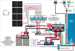
Am I correct? I'll need an RJ45 cable from the Multiplus to the Cerbo, I'm eliminating the VE.Bus Smart dongle as per your suggestion, also a VE Direct cable from the Smartshunt to the Cerbo, I'm assuming the 4x 100/20's will communicate with bluetooth. Is there anything that I'm missing? I've already registered my Cerbo on the VRM. Here is my updated plan that I'm still refining.

Partimewages
Solar Addict
I have no knowledge of the busbar you are using.
Check out the Pike Industries busbars. Recommend highly on this forum. Little more expensive but well worth it.
Check out the Pike Industries busbars. Recommend highly on this forum. Little more expensive but well worth it.
Adam De Lay
Solar Wizard
Correct. I'm not sure on the 100/20s though. As long as they're bluetooth capable, I know they can create a smart network between the shunt and the mppts, but I'm not sure if they'll actually communicate with the Cerbo.Am I correct? I'll need an RJ45 cable from the Multiplus to the Cerbo, I'm eliminating the VE.Bus Smart dongle as per your suggestion, also a VE Direct cable from the Smartshunt to the Cerbo, I'm assuming the 4x 100/20's will communicate with bluetooth.
gr8pix
New Member
They're the SmartSolars, bluetooth capableCorrect. I'm not sure on the 100/20s though. As long as they're bluetooth capable, I know they can create a smart network between the shunt and the mppts, but I'm not sure if they'll actually communicate with the Cerbo.
Adam De Lay
Solar Wizard
Thanks, couldn't tell from the image.They're the SmartSolars, bluetooth capable
Similar threads
- Replies
- 5
- Views
- 415
- Replies
- 2
- Views
- 688
- Replies
- 3
- Views
- 375
- Replies
- 2
- Views
- 447


