diy solar

diy solar

RFI issue

Sounds like you have done well here !

Remember that adding a LOT of turns through the toroid can increase the capacitance from one side of that filter to the other side and possibly have diminishing returns. From S8 to S1 is significant I would say !

Maybe we need to have a DIY ham net some time when the bands are great.

boB
K7IQ
 
Yes it is. I don't understand what you mean by blocking RFI. It is just a switch aiming at bonding neutral and ground in offgrid mode, it has no RFI purpose. I'm confused.
Nevermind. Your EMI filter already couples RF currents from netral to ground. You may want to disconnect SSR control line and see if RFI changes. If SSR is driven by inverter then it could couple inverter RFI into SSR and netural via control line even if SSR input is opto coupled.
 
Remember that adding a LOT of turns through the toroid can increase the capacitance from one side of that filter to the other side and possibly have diminishing returns.
Yes I think around 30 turns is when you start losing isolation to capacitive coupling on HF bands. In my experience 20 - 30 turns gets to close to 40dB of isolation with FT240-31 core.
 
Last edited:
Nevermind. Your EMI filter already couples RF currents from netral to ground. You may want to disconnect SSR control line and see if RFI changes. If SSR is driven by inverter then it could couple inverter RFI into SSR and netural via control line even if SSR input is opto coupled.

I tried to connect and disconnect pretty much everything. Disconnecting the SSR relay does not change RFI in my case.

Concerning other RFI emissions, I've been chasing them down for months now. I replaced a lot of crappy power supplies (switching's) and put some other toroids on cables. I even put all my network hardware (routers, ethernet switch, home assistant - micro PC ...) into a metallic computer case to act as a faraday cage. I managed to choke everything so far. But yeah, what a chore !!! I spent dozens of hours plugging and unplugging every single item, playing with breakers, and walking with the tiny radio around to locate every single problem. It's madness. I though I would turn insane.
 
I spent dozens of hours plugging and unplugging every single item, playing with breakers, and walking with radio around to locate every single problem. It's madness. I though I would turn insane.
It's easy when it's your own house. When you have RFI from neighbors then it gets complicated and you really get to test your diplomacy skills.
 
It's easy when it's your own house. When you have RFI from neighbors then it gets complicated and you really get to test your diplomacy skills.

Yes I can imagine. But luckily it's my house, no neighbors at all.

Your EMI filter already couples RF currents from netral to ground.

Mine seems to not do that. If I don't use a relay to bond, I end up with a floating neutral and like 80 V between neutral-earth and 150 V between live-earth. Instead of 0 and 230 V (We have single phase 230V and neutral from grid transformator to earth and ground from devices to earth).
 
One more thing. When you are done with inverter RFI fix, it would be a good idea to add proper grounding/surge protection on your panels/inverter. Can be done with a bunch of 600V MOVs and 2kV film capacitors for extra RFI bypassing to ground conductor.
 
Mine seems to not do that. If I don't use a relay to bond, I end up with a floating neutral and like 80 V between neutral-earth and 150 V between live-earth.
I meant bypassing of RF current of 1 - 30Mhz , not 50 Hz line freq.
 
One more thing. When you are done with inverter RFI fix, it would be a good idea to add proper grounding/surge protection on your panels/inverter. Can be done with a bunch of 600V MOVs and 2kV film capacitors for extra RFI bypassing to ground conductor

Do you have a link or schematic to show ? I'm not sure that I understand your suggestion.

Thank you for helping again.
 
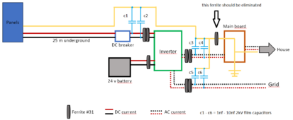
Here is schematic with added filter capacitors. Together with toroid chokes inductance they form an LC filter which may enhance RFI reduction. I would first try 1nF caps and if that does not help try 10nF. I am not sure how much extra capacitance will be tolerated on PV- terminal since that one connects direct across low frequency half bridge and ground and that terminal swings to -450 volts square wave at 50hz. The choke should help out with preventing IGBTs switching into capacitor "short" but that depends on how much impedance that choke creates. Ground conductor choke ideally should be removed since it creates high impedance ground at RF and may negatively impact surge survival from nearby lightning induced spikes. You can add 600V MOVs across each capacitor to help protect against lightning induced voltage spikes. Use Bourns GMOV series of MOVs with built in series spark gap to reduce chance of MOV failing short.

rfi_problemv2-1.png
 
Last edited:
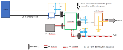
Another way to keep your inverter ground connected to earth ground for safety while keeping high impedance at RF is to install ground choke between inverter ground and capacitors ground connection. This way you keep your inverter earth grounded for safety without creating direct path for RFI. This setup is now becoming "whole" at being RFI proof. Still need to add lightning surge protection at PV side and it will be done.

rfi_problemv2-2.png
 
Last edited:
getting rid of the high frequency inverter
Not optional in OPs case. Besides, this is a good problem to solve because these high-freq AIO inverters are cheaper, lighter and pack more features in compact package than comparable low-freq transformer based solutions. These things are great for helping developing world get solar.
 
Another way to keep your inverter ground connected to earth ground for safety while keeping high impedance at RF is to install ground choke between inverter ground and capacitors ground connection. This way you keep your inverter earth grounded for safety without creating direct path for RFI. This setup is now becoming "whole" at being RFI proof. Still need to add lightning surge protection at PV side and it will be done.

View attachment 208498

Wow that's epic ! thank you, I will study the case. In your proposition, what about the bond between neutral and earth in offgrid mode ? C5 cap would be shorted: could it create imbalance ?


The solution to my RFI problem was getting rid of the high frequency inverter,that took care of the problem 100%.

The equivalent of this hybrid inverter from EU high-quality brand is 3000€ (vs 300 for mine). I cannot justify such an expense to solve a few interferences for a radio hobby (which I can enjoy anyway when going in the mountains).
 
Here is my shopping list, if you approve I can give it a shot.
You should get 600V DC rated MOVs for PV- to ground and whatever is your PV voltage + 100V for PV+ to ground and PV+ to PV-. Would need 3 per side or 6 total. I prefer MOVs with built-in gas discharge tube but GMOV only goes up to 415VDC which is not enough.
 
Last edited:
Back
Top