diy solar

diy solar

Seplos BMS to SunSynk Inverter Cable

k44ent

New Member
Joined
Apr 29, 2023
Messages
10
Location
Uttoxeter, Staffordshire
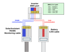
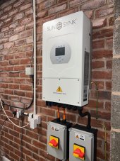
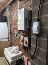
I am very new to all this but am in the process of installing a Seplos 15.5KW battery with a 200A BMS through a SunSynk 8.8 KW Inverter. I understand I need to connect the battery BMS using the CAN port to the inverter. I am not sure what cable I need, is this something I can buy or do I need to make a special RJ45 cable up. Thanks in advance.
 
battery end , normal utp connection

inverter end :
white-blue pin 4
blue pin 5
green pin 6

be careful in the manual the pins are swapped out
 
battery end , normal utp connection

inverter end :
white-blue pin 4
blue pin 5
green pin 6

be careful in the manual the pins are swapped out
The inverter manual says 2-Ground, 4- CAN H and 5 - CAN L and the BMS says 4 - CAN H, 5 - CAN L and 3/6 Ground. Does that sound right?
 
The inverter manual says 2-Ground, 4- CAN H and 5 - CAN L and the BMS says 4 - CAN H, 5 - CAN L and 3/6 Ground. Does that sound right?
the manual of your inverter has the pins swapped...

just told you how i have my 12k hooked up to my seplos's
 
the manual of your inverter has the pins swapped...

just told you how i have my 12k hooked up to my seplos's
Ok thanks, so stick with what you've said. Basically the same at both ends? CAN L - Blue, CAN H - White / Blue, Ground - Green - Ground? Sorry to sound thick but all this is new to me.
 
Last edited:
no, on the battery side use standard pin-out for rj45, as shown in the link.

at the inverter side, crimp on a new rj45 where
white-blue = pin 4
blue = pin 5
green = pin 6
 
Thank you, really appreciate your help. Should I go for a CAT 6 cable?
it depends where and how long your comm cable will be.
if it will be longer than 4m i would, if running through the same conduit as your battery positive and negative, i'd use cat6 Sftp ( extra shielded)
otherwise cat5/5e is just fine
 
it depends where and how long your comm cable will be.
if it will be longer than 4m i would, if running through the same conduit as your battery positive and negative, i'd use cat6 Sftp ( extra shielded)
otherwise cat5/5e is just fine
I'll go CAT 6. Am I ok to use CAT 6 for the CT, the CT cable with the inverter isn't long enough, need to go about 18m. Thanks again.
 
I'll go CAT 6. Am I ok to use CAT 6 for the CT, the CT cable with the inverter isn't long enough, need to go about 18m. Thanks again.
you're welcome and good luck !
make sure to set the ct pointing the arrow in the correct direction..
after done, do share pictures :)
 
you're welcome and good luck !
make sure to set the ct pointing the arrow in the correct direction..
after done, do share pictures :)
Just done a bit more reading and downloaded the latest 8.8kw manual and now I'm totally confused! Is your 12kw inverter the same as my 8.8 in terms of CAN connection? Only info I can find on the 12 says 4 - CAN H, 5 - CAN L and no other pins used? The diagram looks to have the pin numbers reversed as in the connector is upside-down so pin 1 is pin 8. Really don't know what i'm doing with this!

Would a standard cable with pins 1, 2 and 3 disconnected work?
 
Last edited:
Just done a bit more reading and downloaded the latest 8.8kw manual and now I'm totally confused! Is your 12kw inverter the same as my 8.8 in terms of CAN connection? Only info I can find on the 12 says 4 - CAN H, 5 - CAN L and no other pins used? The diagram looks to have the pin numbers reversed as in the connector is upside-down so pin 1 is pin 8. Really don't know what i'm doing with this!

Would a standard cable with pins 1, 2 and 3 disconnected work?
all comm board are the same, i told you already that in the manual hi and low are swapped.
pin 3 and 6 are ground, which is required for the seplos.

as my rs485 needs ground too, i choose to use pin 3 ground from my rs485 and pin 6 for my canbus.

this is now the third time i told you the same, and i consider your question answered :)
 

Attachments

  • bms_port_split-aba788cab23e6f323a2ba62ad4158191.png
    bms_port_split-aba788cab23e6f323a2ba62ad4158191.png
    84.2 KB · Views: 55
all comm board are the same, i told you already that in the manual hi and low are swapped.
pin 3 and 6 are ground, which is required for the seplos.

as my rs485 needs ground too, i choose to use pin 3 ground from my rs485 and pin 6 for my canbus.

this is now the third time i told you the same, and i consider your question answered :)
Sorry, i just don't understand why pins 4 and 5 have to be swapped over at the inverter end. SunSynk 8.8 inverter states Pin 2 is Ground, Pin 4 is CAN H and Pin 5 is CAN L. Battery says Pin 6 is Ground, Pin 4 is CAN H and PIN 5 is CAN L. So surely a case of making a lead with three wires but Inverter 2 to battery 6, Inverter 4 to battery 4 and inverter 5 to battery 5. Or are you saying this is wrong and the battery / inverter info is incorrect and 4 and 5 need swapping over at the inverter end
 
Sorry, i just don't understand why pins 4 and 5 have to be swapped over at the inverter end. SunSynk 8.8 inverter states Pin 2 is Ground, Pin 4 is CAN H and Pin 5 is CAN L. Battery says Pin 6 is Ground, Pin 4 is CAN H and PIN 5 is CAN L. So surely a case of making a lead with three wires but Inverter 2 to battery 6, Inverter 4 to battery 4 and inverter 5 to battery 5. Or are you saying this is wrong and the battery / inverter info is incorrect and 4 and 5 need swapping over at the inverter end
if indeed you have an 8.8 is will be the new generation, and above will apply.
if it is an 8 kw, it is an older generation, and a straight utp cable might work..
i suggest to start tinkering
 
if indeed you have an 8.8 is will be the new generation, and above will apply.
if it is an 8 kw, it is an older generation, and a straight utp cable might work..
i suggest to start tinkering
It was purchased as an 8.8 a few weeks ago, model number is SUNSYNK-8K-SG01LP1-EU so assuming a new generation then no need to swap pins 4 and 5?
 

Attachments

  • inv 1.jpg
    inv 1.jpg
    231.4 KB · Views: 17
  • inv 3.jpg
    inv 3.jpg
    238.9 KB · Views: 17
It was purchased as an 8.8 a few weeks ago, model number is SUNSYNK-8K-SG01LP1-EU so assuming a new generation then no need to swap pins 4 and 5?
a new device and next generation arent the same thing.
a device can be perfectly new, yet comprise of components of an older generation.

mine are sunsynk sun-12k- SG04LP3
 
battery end , normal utp connection

inverter end :
white-blue pin 4
blue pin 5
green pin 6

be careful in the manual the pins are swapped out
Thanks for posting the configuration. I am about to have a Sunsynk 5.5 ECCO commissioned and noticed that the yellow Comms cable to the battery (also a Seplos) is not marked at either end as shown in the manual, so I was a little confused as to its orientation. I will make up an additional Comms cable exactly as you have and hopefully it will connect correctly

Best wishes and thanks again
 
Back
Top