diy solar

diy solar

Single vs. Multiple Class-T Fuses

I understand it might be an overkill, but there’s a few members here that are very insistent and have me paranoid. :) And some don’t even want Batteries in their house. o_O

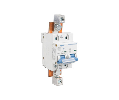
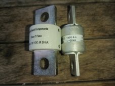
So as I posted, two paralleled batteries (100Ah x 2) per class T fuse. And another class T fuse from the Power In bank to the inverters.

No shunt planned currently.
Yeah, that whole "very insistent" thing got to me a little as well...then tunnel vision kicked in.
I am not technically savvy enough to know one way or the other...so I went back to Victron for their take on it. They were pretty clear. Then I went to someone who has done hundreds of installs for their take. I figure that those guys have a universe more technical knowledge than me. And with all those installs...if something wasn't right with their methodology it would have shown up by now. And they both backed up Will's comment about the battery OCP provided by the BMS. Trifecta of sound practical knowledge :)
I really like that you are stepping outside the box and actually making something. I can appreciate a DIY guy who is hands on. And who knows...maybe you are really on to something! Think patents...and millions ;)
I am really thinking MRBF's on the batteries. But for now I just have to get this upgrade finished...then take a week off from everything!
But please keep me updated on the whole PowerIn / Class-T thing...it sounds really interesting.

{edit} If you get a minute...Why no shunt? What are you going to do for monitoring?
 
I understand it might be an overkill, but there’s a few members here that are very insistent and have me paranoid. :)
You and me both ?
But please keep me updated on the whole PowerIn / Class-T thing...it sounds really interesting.
Your modification of the Lynx Power-In also has me intrigued.
Be nice to see a separate post on how you went about it from beginning to end.
 
Yeah, that whole "very insistent" thing got to me a little as well...then tunnel vision kicked in.
I am not technically savvy enough to know one way or the other...so I went back to Victron for their take on it. They were pretty clear. Then I went to someone who has done hundreds of installs for their take. I figure that those guys have a universe more technical knowledge than me. And with all those installs...if something wasn't right with their methodology it would have shown up by now. And they both backed up Will's comment about the battery OCP provided by the BMS. Trifecta of sound practical knowledge :)
I really like that you are stepping outside the box and actually making something. I can appreciate a DIY guy who is hands on. And who knows...maybe you are really on to something! Think patents...and millions ;)
I am really thinking MRBF's on the batteries. But for now I just have to get this upgrade finished...then take a week off from everything!
But please keep me updated on the whole PowerIn / Class-T thing...it sounds really interesting.

{edit} If you get a minute...Why no shunt? What are you going to do for monitoring?
I have a lot on my plate, so solar is kinda on the back burner for now. But will post pictures when I’m finished.

The guy who I bought the batteries from also thought I was going overboard and mentioned that the BMS is enough. But where is the BMS manufactured…CHINA!? (So are the breakers)

So you be the Judge…:unsure:

I guess when it comes to any potential of a house fire, I open my wallet, if anything just for a piece of mind.


I may add a shunt someday, gonna see if I really need it first.
 
I have a 250A class T right immediately after each 16S pack. I have a disconnect switch that I won't throw without loads shut off first at the inverter.

I thought about breakers but I don't trust all these cheap ones on Amazon, and the should be good ones are more expensive than fuses, so...
 
I have a 250A class T right immediately after each 16S pack. I have a disconnect switch that I won't throw without loads shut off first at the inverter.

I thought about breakers but I don't trust all these cheap ones on Amazon, and the should be good ones are more expensive than fuses, so...

If you have no plans on running more than 100amps per battery, what are the groups thoughts on using a Midnite Solar MNEDC100 as an over current protection device and disconnect switch on a 24v or 48v lifepo4 100ah battery? I think they claim 10,000 AIC at 150vdc.

If that isn't good enough, they have the MNEDCRT 175A to 250A which they claim has 50,000 AIC at 125vdc.
 
Just tried looking up MOSFET MTBF, but the datasheets I found don't have a figure listed. If you figure a 1% chance per year of a MOSFET failure within the array of 40 starting in year five, going up a percent per year, that would indicate an almost 20% chance of a failure within 10 years. AIUI, this kind of failure is also likely to not be seen until something actually goes wrong and the BMS tries to do its job but can't because of the failed MOSFET.

Given we already know people have experienced MOSFET failure, these numbers may be a bit off, but at this point I'd rate the BMS MOSFETs as excellent first line, non-destructive protection, but not so good to rely on for ultimate protection in a multiple failure situation. That's where high-reliability devices like fuses and breakers come in. Thus, I'm with @John Frum on needing something else to back up the BMS.

If someone knows where to find actual MTBF numbers I'll be happy to update this.
 
@TorC Also, remember that if something goes wrong at the inverter and there is back EMF (for example, an overload that causes the inverter to suddenly shut down, suddenly stopping a big DC current at the input) this could cause a voltage spike that makes the MOSFETs of the BMS fail open - and you wouldn't even realize it. System powers back on, everything seems fine, but your BMS is not a protective device anymore...
 
Looking at the breaker route, I found this.
They have paired two together to get the 200 amps. My concern is that they've fitted it for only up to 1/0 wire. Did they limit the terminal because that's all the y buss can handle?
 
They have paired two together to get the 200 amps. My concern is that they've fitted it for only up to 1/0 wire. Did they limit the terminal because that's all the y buss can handle?
It is a single manufactured 200A breaker. It is fairly common for compact breakers to require two pole spaces in width/height for anything over 125A. As for the small lugs, no clue but it looks like you could use aftermarket lugs or even ring terminals if you wanted to.
 
If someone knows where to find actual MTBF numbers I'll be happy to update this.
MTBF on MOSFET if used within SOA is over hundred years.

MTBF is fairly meaningless on Chinese BMS designs, primarily due to lack of heat sinking. Reliability degrades orders of magnitude at very high temperatures.

Most Chinese BMS max current ratings are based on about 20 watts of heating. This is a very large amount of heating for their typically very poor heat sink design with heat sink sponge pad on top of power MOSFET plastic side of case to a skimpy aluminum BMS cover plate. Very poor heat conduction path resulting in MOSFET die inside their epoxy package getting very hot. MOSFET Rds_ON series resistance get greater as they get hotter, about 1.5x room temperature Rds_ON at 100 degs C.

For size reference, a typical stock computer CPU heat sink can dissipate about 15 watts of heating without forced air cooling from a fan. The typical 4" fan forcing air through CPU heat sink takes it up to about 100 watts of heat dissipation.

If you want better reliability do not use most Chinese BMS's above a sustained current (>5 mins) of half their advertised current rating.

JK 16-24S active balancer BMS temp vs current.png

JK 4-8S active balancer BMS temp vs current.png
 
Last edited:
@RCinFLA Great analysis. What do you make of the 30% "recommended" discharge rates from EG4's batteries; is this observing good practice or do you think further de-rating is warranted?
 
MTBF on MOSFET if used within SOA is over hundred years.

MTBF is fairly meaningless on Chinese BMS designs, primarily due to lack of heat sinking. Reliability degrades orders of magnitude at very high temperatures.

Most Chinese BMS max current ratings are based on about 20 watts of heating. This is a very large amount of heating for their typically very poor heat sink design with heat sink sponge pad on top of power MOSFET plastic side of case to a skimpy aluminum BMS cover plate. Very poor heat conduction path resulting in MOSFET die inside their epoxy package getting very hot. MOSFET Rds_ON series resistance get greater as they get hotter, about 1.5x room temperature Rds_ON at 100 degs C.

For size reference, a typical stock computer CPU heat sink can dissipate about 15 watts of heating without forced air cooling from a fan. The typical 4" fan forcing air through CPU heat sink takes it up to about 100 watts of heat dissipation.

If you want better reliability do not use most Chinese BMS's above a sustained current (>5 mins) of half their advertised current rating.

View attachment 144338

And yet... I've done extensive tests on the JK 200A 16S/24S at 200A (and the 100A version) and I've never had the casing reach anywhere near 80C at 25C ambient.
 
@RCinFLA Great analysis. What do you make of the 30% "recommended" discharge rates from EG4's batteries; is this observing good practice or do you think further de-rating is warranted?
For LFP cells the weak link is expansion and contraction of negative electrode graphite when it comes to SoC use range. A full charge cycle, zero to 100% charge, expands graphite by about 11% due to graphite being stuffed with lithium ions. It limits the 2000+ cycle life.

Other Li-Ion chemistries are much more limited in cycle life by their weak cathode lattice structure. It is why EV's, using nickel-based cathodes don't recommend full charging too often. LFP cathode is near bulletproof by comparison.

You run a higher risk of fracturing graphite into electrically isolated chips, or delaminating it from copper foil, the wider the SoC range used.

You have to run the charge near full charge periodically to maintain balancing so that leaves minimizing discharge amount to avoid expansion stressing the graphite.

This is not the only degrading process that can be done. The graphite expansion cracks the protective Solid Electrolyte Interface surface coating the graphite granules. It is regrown on subsequent charging but does consume a small amount of free lithium and degrades electrolyte, reducing capacity of cell, and thickens up the SEI layer, increasing cell impedance. This is primary cause of normal lifetime wear on LFP cells and is unavoidable. Thickening SEI layer and electrolyte degradation shows up as greater cell voltage slump under load current as the cell gets older.

High charge and discharge currents is also stressful on cells.
 
Ordered a new class t fuse for second battery bank and a spare one.

Comparing these fuses puzzled me. One fuse looks much more sturdy than the other one. (see attached picture). The larger one is way heavier than the smaller one.

Anyone an idea if the smaller one still is safe to use wrt breaking capacity?
 

Attachments

  • IMG_20230413_070817.jpg
    IMG_20230413_070817.jpg
    165.8 KB · Views: 14
Ordered a new class t fuse for second battery bank and a spare one.

Comparing these fuses puzzled me. One fuse looks much more sturdy than the other one. (see attached picture). The larger one is way heavier than the smaller one.

Anyone an idea if the smaller one still is safe to use wrt breaking capacity?
The casing doesn't necessarily say much, but I would be curious about the difference in dimensions of the terminals. In lieu of a micro-ohmmeter you could measure voltage drop across the fuses at high current. The impedance is ultimately what matters.
 
The casing doesn't necessarily say much, but I would be curious about the difference in dimensions of the terminals. In lieu of a micro-ohmmeter you could measure voltage drop across the fuses at high current. The impedance is ultimately what matters.
In my battery, I installed a class-t fuse, the cheap one.
Not planning to take it out since it is already in there.

At this moment waiting for new cells for the second battery. Because I want to parallel the batteries and want them to be identical, also the fuse in this battery will be the cheap Class T fuse.

This whole thread started to puzzle me and I want to be 100% sure that I have a safe setup.

Therefore I decided to add a fuse block with holder to the both inverters that are connected to the paralleled batteries.

It is a bit of an overkill, but better safe than sorry.

The new fuses and blocks are more expensive, but compared to the fuses in the batteries they look and feel much better and safer. Just a world of difference.
 

Attachments

  • IMG_20230425_110621.jpg
    IMG_20230425_110621.jpg
    217.7 KB · Views: 15
  • IMG_20230425_110636.jpg
    IMG_20230425_110636.jpg
    238.9 KB · Views: 15
Looking at the breaker route, I found this.
They have paired two together to get the 200 amps. My concern is that they've fitted it for only up to 1/0 wire. Did they limit the terminal because that's all the y buss can handle?
Im interested in using 3x of the breakers from Sig Solar in a large Din Rail enclosure for my 3 parallel banks. With a 350-400a Class T Fuse between the breakers and the inverter. I would remove their little 1/0 clamp and just bolt my wire terminal direct to the copper bus they have installed in the breaker.

Anybody see this as a bad thing? Looking at getting this enclosure with it.
 
Back
Top