diy solar

diy solar

Someone told me to buy these, now what?? Need help with lug connectors

Dielectric grease is non conductive and if used properly and in the appropriate circumstances okay as long as it does not form an insulating layer between & amongst the conductors and the connection. ~ When a manufacturer provides a wire terminal connection on a device it is unwise to take it upon ourselves to modify and exceed the gauge, therefore, potential amperage of the connector as built.

You are certainly free to do what you think is right.

There are places I won't use grease, it's simply not needed,
Other places it not appropriate.

Consumer 'Battery Cable' is thicker stands (opposed to something like welding cable) and I find the strands mash the grease out at contact points, but stays between strands where moisture can enter/corrode.

In most cases,
Manufacturers don't apply things like Never-Seize, Thread Locker, Oxidation Guard, Dielectric Grease simply because it costs time & money.
Anyone that's ever had to work on an old vehicle or equipment is most certainly aware of rusted/corroded in bolts, corroded out electrical connectors, twisted off fasteners, etc...

For instance, I won't put a steel bolt in aluminum without either thread locker (seals out moisture as well as keeping the bolt in) or Never-Seize to keep that bolt from galvanic corrosion lock into the aluminum.
I've got 3 aluminum engine timing covers with water pump bolts twisted off in them right now in the shop, the flowing coolant increases the galvanic issues and bolts ALWAYS corrode solidly into these timing/pump covers.
While it's a steady income stream for me, it takes very particular tools to repair those covers, which are for 'Vintage' engines not made since 1990.

Any & every outdoor electrical connection I do gets protected.
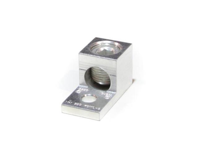
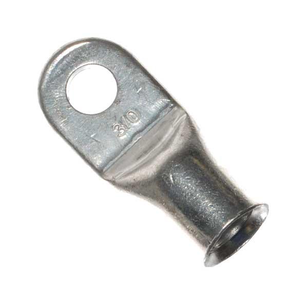
Aluminum cables get Oxi-Guard when they clamp in lugs,
Copper wires get tinned, Oxi-Guard, or Dielectric grease.
I learned this the hard way, since humidity, fog, rain gets everywhere no matter what, and DC electrical connections don't handle it well, much worse than AC wiring.

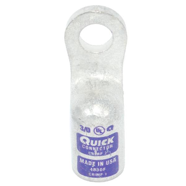
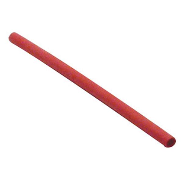
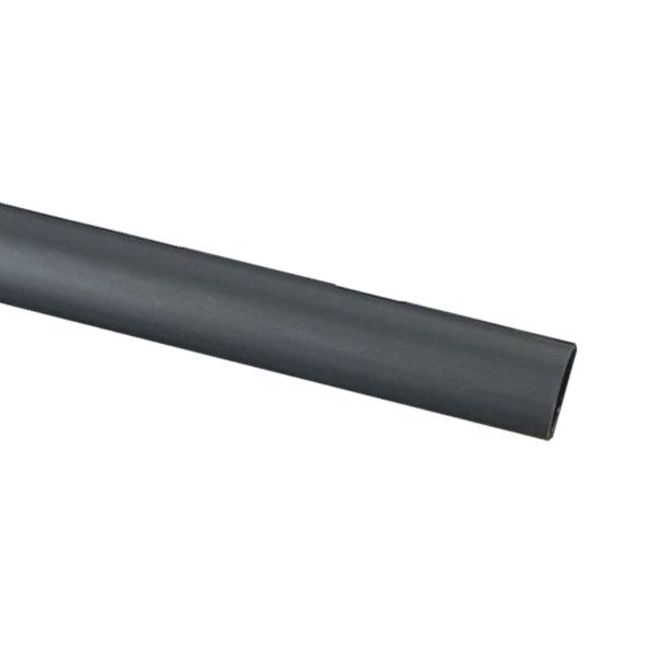
It's like the guff I take about lead/acid battery connections, solid, plated connector, heavy crimp (mechanical connection), silver bearing electrical solder, then glue filled heat shrink tubing...
Then seal up between battery post & case with the spray on goop, make connection, and spray everything to seal it up.
While other people schedule regular replacement ends, I clean mine every year or two, seal them back up and some have been around for 15 years (or more).

WinchInstall09.gif

WinchInstall11.gif

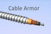
THIS is what happens when just moisture/water gets into a terminal/cable bundle...
And this should explain WHY I learned to seal everything up against DC & moisture.

WinchInstall12.gif
 
I added the specs at my original post: 2 Battle born 100 Ah, 400 watts solar, 2000/4000PEAK pure sine wave inverter, Renogy DC-DC alternator MPPT Controller (there are 2 fuses and a circuit breaker in Wills blueprint and I'm adding a fusebox too.) May I ask if you looked at the blueprint? What is armoring? Sorry about the rats.
Armoring is using metal conduit, usually flexible to route the wire protected.
 
Armoring is using metal conduit, usually flexible to route the wire protected.

Actually 'Armor' is a generic term for extra protection other than electrical insulation.
Rigid or flexible (metal or plastic) conduit,
In race cars, we use layered laminated liquid pressure hose (steel braid/Teflon lined) to prevent the battery cables rear to front from being cut into in a crash.
 
Last edited by a moderator:
Actually 'Armor' is a generic term for extra protection other than electrical insulation.
Rigid or flexible (metal or plastic) conduit,
In race cars, we use layered laminated liquid pressure hose (steel braid/Teflon lined) to prevent the battery cables rear to front from being cut into in a crash.
Yeah, but to keep critters out, like was posted... steel, or aluminum would be my choice!
 
Yeah, but to keep critters out, like was posted... steel, or aluminum would be my choice!

I will go with that!

Stainless Steel braided line will stop rodents also, wears their teeth out.
Ask me how I know that... ;)

For whatever reason, rodents won't chew silicone vehicle heater hose available at about any any parts store.
Don't ask me why, but I've had two vehicles nearly completely stripped of insulation and hose, but they wouldn't touch the silicone heater hoses, gnawed on the steel braid but didn't get through it.
So much for storing project cars in a pole barn...
You ought to see my vette!
 
If I may lay out The Confusion,

A1HA_1_20180417702637632.jpg


1. This lug is in question.
Apparently the inverter doesn't support 000 (3/0) Ga. or 0000 (4/0) Ga. cables and will need an oversize lug connected to the inverter terminal to accept a bare cable (no ring terminal that bolts directly on).

For cable ends I would have recommended something practical, like a plated, solid copper that would carry the current, but the Original Poster (OP) give details and we had to guess at application.

View attachment 2158

2. GREASE.
The lug above was still in dispute, could very well have been used in a wet/rain/corrosive environment, and it's common usage to use protective coatings on lugs/terminals/exposed conductors.

Oxidation/Corrosion control grease is conductive, you DO NOT use conductive grease where it can migrate (run) from one terminal to another. Period.
(See picture of stacked terminals on inverter & charge controller.
Non-conductive Dielectric grease or other non-conductive terminal protector when multiple terminals are in close proximity.

On copper wires you can 'Tin' the wire, or you can use a little dielectric grease.
As mentioned above, dielectric grease is very low viscosity and the mechanical force of the screw terminal will make a fine connection in spite of the grease.

For those that think dielectric grease will inhibit a connection, I would point out the best quality terminals that crush, mash and screw terminal types come Pre-Loaded with Dielectric grease...
Please let me see if I follow you: Actually, yes these lugs I bought support 4/0, 3/0, 2/0, and 1/0- Are you meaning the inverter won't accept a 3/0 or 4/0 terminal? Here is exactly the lug I bought from EBAY: https://www.ebay.com/itm/231932273027 I am a bit confused, but learning and absorbing like a sponge. I appreciate your patience and information. (everyone else trying to help too!) I will get whatever is the best thing to buy. I am understanding that you think I should either bring the circuit breaker closer to the battery, but how close?, but then the blueprint will be completely different. (I would need a visual to see how to change it. If I am understanding you, you think the positive wire from the battery to the breaker is dangerous being left uncovered. You think I should cover the positive battery wire with something as an option. Am I right?
 
Last edited:
Dielectric grease is non conductive and if used properly and in the appropriate circumstances okay as long as it does not form an insulating layer between & amongst the conductors and the connection. ~ When a manufacturer provides a wire terminal connection on a device it is unwise to take it upon ourselves to modify and exceed the gauge, therefore, potential amperage of the connector as built.
This is better...https://www.youtube.com/watch?v=3VtfqAym5sQ
 
Please let me see if I follow you: Actually, yes these lugs I bought support 4/0, 3/0, 2/0, and 1/0- Are you meaning the inverter won't accept a 3/0 or 4/0 terminal? Here is exactly the lug I bought from EBAY: https://www.ebay.com/itm/231932273027 I am a bit confused, but learning and absorbing like a sponge. I appreciate your patience and information. (everyone else trying to help too!) I will get whatever is the best thing to buy. I am understanding that you think I should either bring the circuit breaker closer to the battery, but how close?, but then the blueprint will be completely different. (I would need a visual to see how to change it. If I am understanding you, you think the positive wire from the battery to the breaker is dangerous being left uncovered. You think I should cover the positive battery wire with something as an option. Am I right?

What *I* (personally) would do is use a ring terminal on the cable and forget the lug.

This shows a round battery clamp on the cable, but I show a ring terminal that could be used for your application.

WinchInstall11.gif

While I see are lot of people 'Up' on what's being made, and that's all good information.
It's the details on the small stuff that get overlooked,
People don't know about the alloy wire (not pure copper), the availability of terminals for applications, the difference between the 'Cheap'/'Common' terminals and the top shelf/top end stuff you have to hunt around a little for...
Like the conversation about terminal grease for instance...

Just some of the high amperage DC terminals I use, connectors, etc.
I learned to use them from heavy industrial applications, used there because of adverse conditions and heavy use (duty cycle).

WinchInstall01.gif

The (flattened tubing) terminal on left is most 'Common' but it has issues which I can explain in detail if interested.
The second left is a heavy copper, plated against corrosion, and it's used for series connections when full amperage load is needed.

This is what I use on parallel battery strings between terminals.

I also use these when battery strings connect to main lines to the inverter, with the large surface area and thickness of the single ring terminals this makes a 3 wire 'T' connection that will carry full amperage.
The mains run along in front of the battery strings, the strings bolt into the series terminals.

Stacking single terminals on posts creates electrical resistance and multiplies potential for corrosion creating even more electrical resistance.
Electrical resistance in a DC, solar powered circuit wastes you expensive and hard won current as heat and cripples the load carrying capacity of your expensive cables/terminals.
It's a case of "Buy Once, Cry Once" and not sitting in the dark while you try and track the failure (which I did a lot of when I started).

---------

The circuit breaker *Should* (ideally) be attached to the breaker so it protects the entire inverter cable.

In the real world (not ideal),
*I* (personally) armor what's not protected by the circuit breaker.
Someone can lay out a build but not anticipate what *Can* happen, rodents, car crashes, the insulation getting rubbed through, water leaks/condensation, all the things that happen in real life.
 
Last edited:
As an example,
Look at the small surface area around the copper terminal bolt hole.
Small contact patch means lowered ability to conduct amperage between battery and terminal, or between ring terminals in a stack.

For lead/acid batteries, notice the separation line in the flattened tubing.
That's a highway directly to the wire conductor for battery acid, and if you don't believe acid will eat it's way right up that separation line because it's mashed too flat, keep in mind that same acid crawled out of the batter between terminal material the plastic case was molded around/stuck to/sealed with...

WinchInstall25.gif

The large surface (and solid/thick body-neck) of the other terminals allow for MUCH more current to pass between terminals.
These terminals are also hard enough they don't mash out, distort, significantly deform to further screw up the contact surface area.

Silver being a better conductor of electrical current that copper, using silver plated terminals (and solder) makes sense to get your expensive & hard won current where it belongs.
Silver cadmium plating on these terminals, Silver Bearing Electrical solder to make the electrical connection and seal up your terminal connections/tin the wire with.

Something as simple as brass bolts/nuts instead of steel makes your terminal connections more electrically conductive.
You see a LOT of steel, aluminum, etc on consumer electronics, but heavy industrial you won't see electrically resistive and corrosion prone nearly as much.
Electrical connections aren't 'Structural', so steel bolts aren't needed, brass more closely matches the terminal materials and conducts current better.

Take a look at the big, old DC generator equipment from 100 years ago, Edison & Tesla/Westinghouse generators are still in use for subways trains, electric busses, trollies all over the world,
Original brass bolts & copper terminals that still function like new.

I like to say, 'Available' doesn't mean 'Suitable' or 'Optimum',
Spend money on 'Foundation' not 'Decoration'.
 
This is an example of how NOT to make a cable/terminal connection.
This is pre-made, 'China' generic 'Better' cables...

1. The tubing for the terminal is 'Mystery Metal' (NOT copper).

2. The flattening/punching machine knocked a hole in the tubing creating a super highway for corrosives to enter the cable.

BadTerminals03.gif

3. The cable isn't soldered into the terminal, mechanical crimp connection only.

4. The crimp on the cable left bulges/pockets to catch water/corrosives and hold them against the copper (?) wire.

5. The 'Copper' wire is an alloy, 13 Ohms resistance per foot.
Alloyed with who knows what...

6. The heat shrink tubing was 'Decoration', and maybe insulation...
It certainly wasn't glue lined, heavy duty or sealed the connection like it should have.

There is a reason I researched wire & terminals and leaned to make my own battery/high amperage DC cables...
Alloyed wire *Might* work for AC, but it's a disaster for high amp DC.
Aluminum/Alloy really has no place in *MY* DC systems, everyone will have to decide for themselves what they want to do.
 
This is an example of how NOT to make a cable/terminal connection.
This is pre-made, 'China' generic 'Better' cables...

1. The tubing for the terminal is 'Mystery Metal' (NOT copper).

2. The flattening/punching machine knocked a hole in the tubing creating a super highway for corrosives to enter the cable.

View attachment 2187

3. The cable isn't soldered into the terminal, mechanical crimp connection only.

4. The crimp on the cable left bulges/pockets to catch water/corrosives and hold them against the copper (?) wire.

5. The 'Copper' wire is an alloy, 13 Ohms resistance per foot.
Alloyed with who knows what...

6. The heat shrink tubing was 'Decoration', and maybe insulation...
It certainly wasn't glue lined, heavy duty or sealed the connection like it should have.

There is a reason I researched wire & terminals and leaned to make my own battery/high amperage DC cables...
Alloyed wire *Might* work for AC, but it's a disaster for high amp DC.
Aluminum/Alloy really has no place in *MY* DC systems, everyone will have to decide for themselves what they want to do.
I will re-read your posts tomorrow. What do you suggest buying and where? There aren't brass terminals are there?
 
I've got 3 aluminum engine timing covers with water pump bolts twisted off in them right now in the shop, the flowing coolant increases the galvanic issues and bolts ALWAYS corrode solidly into these timing/pump covers.
While it's a steady income stream for me, it takes very particular tools to repair those covers, which are for 'Vintage' engines not made since 1990.
Sorry off-topic...

Working on aluminum boat blocks over the decades I became pretty good at drilling and tapping snapped off steel bolts. But over the past few years I've been using acid more and more, ever try the stuff? A few years ago I snapped a hardened steel tap deep in a blind hole that was impossible to get to, or drill through...I thought I was screwed. I ended up using a product called Tap-X, which is just a combo of readily available acids that eat carbon steel and leave aluminum unharmed. Since then I've used it to remove some steel bolts on delicate jobs where I wanted to leave the original threads intact- I just drill a hole through the snapped bolt and feed acid in every couple hours and the bolt falls out after a day or two. You may have tried it already, but if not add some to your toolbox!
 
I will re-read your posts tomorrow. What do you suggest buying and where? There aren't brass terminals are there?

The battery will probably have a 3/8" hole.
3/8" brass bolts & nuts are common from any online retailer or big box store bolt & nut rack.

This will be an "It Depends" situation, with VARIABLES...

1. Battery Box.
With a battery box in a trailer, camper, RV,
The battery CABLE will have to come through a wall, floor etc.
That means ARMOR/Protecting for a cables that will be there FOR YEARS,
Will have vibration, sharp edges etc to contend with.

I personally would use a 3/8" hole ('eye') ring terminal,
And I would use a heavy lug so it lived longer in UN-Heated/No Climate controlled space (Battery Box).

I would use something like this in the battery/battery box end of that cable...

76-8308_2.jpg

https://www.electricalhub.com/generic--tinned-copper-heavy-wall-lug-2

This one is a blind socket, no place for moister or acid to creep into the cable from the battery end,
Heavy plated solid copper lug body so repeated cleaning won't wear the terminal into junk,
And it's tin plate, so as well as crimped, it can easily be soldered as well as crimped.
(Crimp = Mechanical Connection.... Solder = Electrical Connection & Environment Protection)

I would also seal up anything outside the climate control with Glue Lined Heat Shrink, using Red & Black to denote positive & negative connections.

3_1_red_heat_shrink_2.jpg

https://www.electricalhub.com/3m/polyolefin-dual-wall-heat-shrink-tubing/eps-300-3-4-48-red

20-3340.jpg

https://www.electricalhub.com/3m/polyolefin-dual-wall-heat-shrink-tubing/eps-300-3-4-48-black

Since the LiFePo4 batteries don't have ACID corrosion problems at the terminals,
BUT,
Those 3/0 or 4/0 cables are stupid expensive, good solid heavy terminals crimped/soldered & heat shrink *Should* live as long as the vehicle...

--------------

2. Batteries inside the vehicle (mostly dry, climate controlled).
I never recommend batteries in a living compartment, I'm only doing this because I don't know specifically what you intend to do...

I would still use brass bolts/nuts at the battery connections.
Even more important with thinner, lighter duty lug terminal ends.

This is what I would use and the 'eye' is a 3/8" hole for the battery connections.
(The rest of the system *Probably* won't have 3/8" bolts, oversize holes are connection surface area lost)

76-3038.jpg
 
3. At circuit breakers, inverter, charge controller, measure the bolt/stud sizes and order terminals with the correct size 'Eye' holes.
Oversize holes are wasted contact area.

I often buy smaller 'Eye'/bolt hole sizes and drill them out to what's needed so I don't have to stock as many types/sizes.
Drilling is perfectly acceptable, although in hard copper/brass/bronze it can be difficult.
(If you want to see how hard brass can be, try drilling a pre '82 penny!)

As shown in the diagram the OP posted links to, the bare copper terminals are acceptable INSIDE climate controlled conditions.
If the camper/trailer/RV sits unheated for long periods, it's simply isn't that expensive to use plated terminals.

I still recommend you crimp, solder and color code heat shrink.
Leave some extra slack in your cables, 3"-4" or so, this allows you to replace terminals when necessary without scrapping your expensive cables.
 
4. Reducing connections and common sense.

Take a look at the inverter Negative Cable in this picture.
It connects to battery, up through buss bar, then through buss bar, then another cable to inverter....

Battery terminal --->Cable Terminal ---> Cable to buss bar terminal --->Buss Bar to cable terminal --->Cable to inverter Terminal On Cable --->Inverter Terminal.

dfsdfd_orig.jpg


Anyone see anything wrong with this? 4 bolted together terminal connection points on one high amperage cable...

Using a 3/0 cable, and a 4/0 ring terminal at the inverter end, simply slip the 3/0 AND 4 Ga. Cable into the lug, crimp both wires at the same time and crimp.
This gives you a direct, solid connection of the 4 Ga. Cable to charge controller/battery cable without the buss bar & its connections. Buss bar completely elminated.

*IF* you want to tap the negative cable for 12 Volts,
The Charge Controller negative cable (4 Ga.)
Simply slip a 10 Ga. wire in with the 4 Ga. and crimp.
Now you have a 10 Ga. Negative for 12 volt appliances inside the camper/RV/Trailer.
All directly connected to the battery negative source by solid connections instead of stacked ring terminals.

MUCH cleaner install without all the short start-stop wiring.
 
Silver being a better conductor of electrical current that copper, using silver plated terminals (and solder) makes sense to get your expensive & hard won current where it belongs.
Silver cadmium plating on these terminals, Silver Bearing Electrical solder to make the electrical connection and seal up your terminal connections/tin the wire with.
I would be quite surprised if the plating is silver. Most common coating is tin...
 
As an example,
Look at the small surface area around the copper terminal bolt hole.
Small contact patch means lowered ability to conduct amperage between battery and terminal, or between ring terminals in a stack.

For lead/acid batteries, notice the separation line in the flattened tubing.
That's a highway directly to the wire conductor for battery acid, and if you don't believe acid will eat it's way right up that separation line because it's mashed too flat, keep in mind that same acid crawled out of the batter between terminal material the plastic case was molded around/stuck to/sealed with...

View attachment 2186

The large surface (and solid/thick body-neck) of the other terminals allow for MUCH more current to pass between terminals.
These terminals are also hard enough they don't mash out, distort, significantly deform to further screw up the contact surface area.

Silver being a better conductor of electrical current that copper, using silver plated terminals (and solder) makes sense to get your expensive & hard won current where it belongs.
Silver cadmium plating on these terminals, Silver Bearing Electrical solder to make the electrical connection and seal up your terminal connections/tin the wire with.

Something as simple as brass bolts/nuts instead of steel makes your terminal connections more electrically conductive.
You see a LOT of steel, aluminum, etc on consumer electronics, but heavy industrial you won't see electrically resistive and corrosion prone nearly as much.
Electrical connections aren't 'Structural', so steel bolts aren't needed, brass more closely matches the terminal materials and conducts current better.

Take a look at the big, old DC generator equipment from 100 years ago, Edison & Tesla/Westinghouse generators are still in use for subways trains, electric busses, trollies all over the world,
Original brass bolts & copper terminals that still function like new.

I like to say, 'Available' doesn't mean 'Suitable' or 'Optimum',
Spend money on 'Foundation' not 'Decoration'.
Will just updated the blueprint here: https://www.mobile-solarpower.com/simplified-400-watt-fewer-wires-and-alternator-charging.html I appreciate all the time and effort you and everyone posted here. EDITED
 
Back
Top