diy solar

diy solar

Upgrade my sub panel box?

Jdcarrol

New Member
Joined
Aug 5, 2023
Messages
49
Location
Phoenix
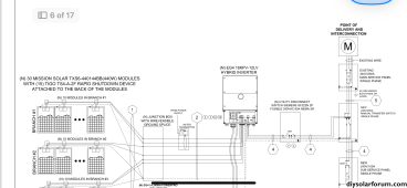
The city has approved my plan and I’m ready to connect everything. My plan was built by SanTan Solar and they were great to work with. I am performing an off grid set up. My home has a main and sub panel breaker box. I plan on connecting my PV system to the sub panel for now and not power the whole house via my system. I’d like to see if I can pull off a partial load before committing to a whole house load, especially with the electrical intensive Phoenix Arizona area.

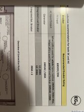
My sub panel is rated at 120/240v and 125amp max. Per my eg418kpv user manual, for partial home loads I do not need a 200amp breaker box bus bar, it states 100amp for partial loads.

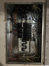
So my question is, do I not need to upgrade my sub panel box? Until last night I thought I had to upgrade to a 200amp box. See photos for more.
 

Attachments

  • IMG_4596.jpeg
    IMG_4596.jpeg
    626.9 KB · Views: 15
  • IMG_4595.jpeg
    IMG_4595.jpeg
    743.1 KB · Views: 15
  • IMG_4593.jpeg
    IMG_4593.jpeg
    798.1 KB · Views: 15
The subpanel is supposed to be sized based on a calculation that accounts for all the loads with a percentage factor. Assuming the 125A subpanel is sufficient for the proposed loads it doesn't need to be upgraded.

An electrical circuit must be protected by an overcurrent device selected based on the LOWEST current rated device in the system. If there is going to be utility power delivered to the inverter AC input then a breaker at the source (main panel) has to be sized so that the sum of pass-thru and inverter power, when blended, does not exceed the subpanel bus bar rating.

I don't believe the 120% rule applies here since the inverter is a single a source of power as far as the subpanel is concerned.
I’m not changing the loads on the sub panel, just changing the source of electricity from grid to off grid PV. So sounds like I just saved myself some money and headache?
 
Can a main breaker be installed in the sub panel?

That would protect the sub panel if more than 125A is available. It would also allow interlocking with a backfed "generator" branch circuit breaker, which could be used to by pass the inverter if that is out of service.
 
Can a main breaker be installed in the sub panel?

That would protect the sub panel if more than 125A is available. It would also allow interlocking with a backfed "generator" branch circuit breaker, which could be used to by pass the inverter if that is out of service.
Here’s a part of the schematic. We do have a utility disconnect switch and manual transfer switch. Does that provide the scenario you describe?
 

Attachments

  • IMG_4597.png
    IMG_4597.png
    419.5 KB · Views: 16
Yes. That is a better switch.

Interlocked breaker is cheaper (about $100 for interlock kit and a branch breaker), and while bezel is removed there is nothing to prevent turning on both sources, which will blow of the inverter.

Schematic shows 60A breaker in new 100A sub panel. Your existing sub panel has no main breaker (yet). I would install the biggest it takes, e.g. 100A, and size wire accordingly.

Depending on battery capacity, you may find it useful to separate critical loads from less important backed up loads. Of course you could manually switch them off. My inverter has signal relays for two different SoC. That could keep communications always on while shutting off laundry. Something like HVAC has a low voltage thermostat signal you could switch.


Feeds through existing main service panel. 60A is a bit over the 40A allowed by 120% rule for 200A panel with 200A main breaker. Are you allowed to do this by not having any other branch breakers in it? If so, at this time you never have more than 60A connected to grid, and a smaller main breaker in main panel would allow other loads on main panel.
For battery, I am currently planning on one eg4 power wall (14.3kwh). Can you help me understand the last paragraph you shared? I don't quite understand. If you're up for it. I can DM you and share the entire design plan that provides more detail if you're up for looking.
 
For battery, I am currently planning on one eg4 power wall (14.3kwh). Can you help me understand the last paragraph you shared? I don't quite understand. If you're up for it. I can DM you and share the entire design plan that provides more detail if you're up for looking.


280 Ah 48V battery.
Think it will supply everything overnight? I have a bunch of inefficient refrigerators, also yard lights. Can't make it through the night unless some turned off.
During inclement weather, PV won't keep up. You should plan to turn things off, ideally have SoC based automatic load shedding.


"Feeds through existing main service panel. 60A is a bit over the 40A allowed by 120% rule for 200A panel with 200A main breaker. Are you allowed to do this by not having any other branch breakers in it? If so, at this time you never have more than 60A connected to grid, and a smaller main breaker in main panel would allow other loads on main panel."

What will be connected to your main panel (which you identify as 200A)?

Just a 200A main breaker, and lugs at the other end of bus to feed transfer switch?
Or are there other branch breakers?


Does the inverter backfeed the grid? Or does it only provide a UPS function plus PV for downstream loads?
(When backfeeding, there are rules regarding multiple breakers putting current into the panel.)
Thank you for the continued support, Hedges. The inverter will not backfeed to the grid. The idea with that manual transfer switch being that if the PV system can't keep up that I flip that switch and have the sub panel be powered by the main panel as currently exists.

My hope is that the 14.3kwh batter is enough to get through the night here in phoenix, it's not our whole house, but is enough to be a whole house elsewhere. There is a 2 ton HVAC, electric water heater, clothes dryer, and general electric for 1/3 of the houes.

Can you healp me understand what you mean by SoC based automatic load shedding?
 
Not backfeeding means "120% rule" doesn't apply, and you're free to have other loads on that main panel.

If battery gets low, say 30% SoC, you might want to have power cut to most loads, refrigerators, lights, etc. and just keep internet/alarm/garage door, minimal lighting. You could run your heating/cooling loads for a while but maybe not long. The water heater and clothes dryer in particular ought to be run only when there is PV producing, unless dryer can complete a cycle and leave you with enough power. Water heater ought to be treated as additional energy storage, only "charged up" with sunshine available.

My inverters estimate SoC by voltage and coulomb counting. BMS of lithium batteries would take care of that. If you have output signals like my inverters do, they can be used to "shed" larger loads. Right now, mine sheds 100% of loads but keeps AC coupled PV connected; I want to make it more selective.

Also, at high SoC or when PV production is being curtailed due to full battery, you might want to enable a dump load (e.g. electric water heater).
I think I’m starting to understand what you’re saying, and also opening a whole new world of PV strategy that makes complete sense, but I don’t understand how you pull it off.

From my understanding my eg4 18kpv and eg4 power batter should communicate very well….but how are you selectively choosing which appliances to power/when? For example. In Arizona if the SOC is high, I’d love to just shed it to the hvac to cool the air.

How are you selecting which appliances to feed to or turn off without manually going out there and flipping breakers or cracking the thermostat down?
 
I'm not, yet. Just disconnecting everything with a relay until sun comes up and SoC recovers.

Assuming you have control signals (my inverters each have 2x SPDT relays), those can go to a power relay. They could also simply interrupt a thermostat signal.

Some people have home automation smart switches.

I'd like to have a continuously variable load, like VFD water pump or HVAC compressor, or dimmer feeding heating element. Control of that to keep PV MPPT at maximum power when battery demands less would be more challenging.

Anyone with Raspberry Pi or whatever that can query SoC could implement switching.

Given lithium battery which can cycle without much wear, turning loads on and off with hysteresis should work.

At a minimum, you could enable/disable based on battery voltage at two points on the knee of the curve. But you'd like something that counts coulombs as well, because voltage is a poor indicator in middle of SoC range.
Thank you for your support today, it's been very helpful :)
 
Back
Top