diy solar

diy solar

Option to bypass inverter - Transfer switch?

thats not nearly as bad as I thought it would be.

edit: sounds like something I said before my first divorce was finalized.
I like these units because if I ever have to bypass the inverter and put things on utilities it's very easy. There is also times when I'd rather have more or less things on solar, depending on my battery SOC, inclement weather, etc. I like the ability to control each circuit.
 
I like these units because if I ever have to bypass the inverter and put things on utilities it's very easy. There is also times when I'd rather have more or less things on solar, depending on my battery SOC, inclement weather, etc. I like the ability to control each circuit.
I fully appreciate that setup, trust me, i was joking about something I said during my divorce, that proved to be very wrong when all was said and done. :cry:
 
I like these units because if I ever have to bypass the inverter and put things on utilities it's very easy. There is also times when I'd rather have more or less things on solar, depending on my battery SOC, inclement weather, etc. I like the ability to control each circuit.
A question, I bought this: https://www.amazon.com/dp/B0CJ8W97MV?psc=1&ref=ppx_yo2ov_dt_b_product_details which looks very similar to yours... Diagram indicated to connect neutral from the transfer switch circuit into the grid panel neutral. But some of my arc breakers are getting activated. How did you handled that neutral? or did you experienced any issue like the one I mentioned?
 
The Reliance transfer switch only switches L, or L1/L2 for 240V loads.
It leaves N connected in the original panel.

See if you can repurpose a 2-pole transfer switch in the Reliance for L/N of the AFCI and/or GFCI breakers.
 
A question, I bought this: https://www.amazon.com/dp/B0CJ8W97MV?psc=1&ref=ppx_yo2ov_dt_b_product_details which looks very similar to yours... Diagram indicated to connect neutral from the transfer switch circuit into the grid panel neutral. But some of my arc breakers are getting activated. How did you handled that neutral? or did you experienced any issue like the one I mentioned?
The Reliance transfer switch only switches L, or L1/L2 for 240V loads.
It leaves N connected in the original panel.

See if you can repurpose a 2-pole transfer switch in the Reliance for L/N of the AFCI and/or GFCI breakers.
Yes hedges is right.

I was lucky I got away with sharing my neutral across all my panels and MTS’s without it bothering any of my GFI breakers on my main. I’ve seen some GFI breakers be more sensitive to this in other buildings I’ve worked in, last one was a bad neutral ground bond on a bad circuit causing the trip, we could never find it on the run so settled with gfci outlets at the ends of the run. Not elegant but we moved on
 
Last edited:
@Hedges @Mattb4 @meetyg
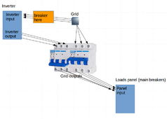
Reposting the wiring diagram you approved, and I have a question. So I'll have 2 sets of 3 wires leaving the 2 outputs of the transfer switch going to a single input on my loads panel. What's the best way to handle this?

Three options I can think of:
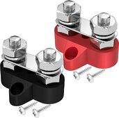
1. putting ring terminals on the wires and using 3 terminal blocks (see picture of terminal block)
2. crimping 3 wires into a "Y cable" (creating 3 "Y" cables)
3. running 2 sets of wires into the inputs on my loads panel (assuming 2 wires will fit)

I'm leaning toward #2 because crimping can probably create the best possible connection between the wires.

correct-transfer-switch.png

terminal-block.jpg
 
Last edited:
Those terminal blocks are meant for low voltage, not exposed hazardous voltages.
You can find set-screw types that accept your wire gauge, and have a cover.

US code says not to put two wires into one terminal that isn't rated for it.
I'd be tempted to strip 1" of insulation off the middle of a wire, fold it in half, twist, and insert in Breaker (RCD) terminals.
Viola! A "V" (use similar to "Y") connection.

I also use multi-port set-screw connectors (Polaris), or split-bolts wrapped in rubber tape then vinyl tape.
 
I'd be tempted to strip 1" of insulation off the middle of a wire, fold it in half, twist, and insert in Breaker (RCD) terminals.
Ok that is next-level genius. Great idea.
 
Does something like an RCD have defined "input" and "outputs" or either set of terminals can be used as the input or output?
 
Those terminal blocks are meant for low voltage, not exposed hazardous voltages.
You can find set-screw types that accept your wire gauge, and have a cover.

US code says not to put two wires into one terminal that isn't rated for it.
I'd be tempted to strip 1" of insulation off the middle of a wire, fold it in half, twist, and insert in Breaker (RCD) terminals.
Viola! A "V" (use similar to "Y") connection.

I also use multi-port set-screw connectors (Polaris), or split-bolts wrapped in rubber tape then vinyl tape.
According to my local regulations, we are allowed to put two wires in the same terminal, as long as they are the same guage.

If you do go this way, make sure to tighten well, and then pull on each wire separately, to make sure it has a good connection.

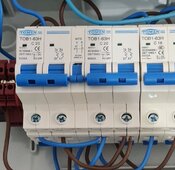
But this two wires don't necessarily need to go to your loads panel, you could just jumper the outputs, Neutral to Neutral, Line to Line, etc. That way you have less wires to run to your panel (only 1 set).

Look at how my outputs (bottom of the transfer switch) are wired:
SmartSelect_20240516-051255_Gallery.jpg
 
Does something like an RCD have defined "input" and "outputs" or either set of terminals can be used as the input or output?
Depends on your specific equipment. Some RCDs have "Line" and "Load" or "Input" and "Output" markings.
If your specific RCD doesn't have such markings, I guess it matters less.
 
you could just jumper the outputs, Neutral to Neutral, Line to Line, etc. That way you have less wires to run to your panel (only 1 set).
I like that option. Thanks for that idea! Picture was helpful too.
 
Is there any reason I can't use the RCD I purchased as the on/off breaker for the inverter input?
It looks like it would function fine for that purpose.
On my main panel it has a 60A breaker before the RCD, which makes me wonder if a breaker should come first.
 
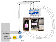
@timselectric @Hedges @meetyg For the sake of any noobs like me who might need to wire a similar circuit, here's my bypass wiring diagram. I need an RCD because that's how it's done in Japan. Any critiques or suggestions for improvements would be appreciated!

final-wiring-transfer-v2.png
 
Back
Top