You may not have read the full thread. It all started with my plan to use the 8 Eve LF280K cells that I have in series for a 24V battery and I was asking about a 12V to 24V converter so that I could charge the battery from my alternator with a DC to DC charger. After discussion and thought I started shifting my approach to go 12V rather than 24V and then the discussion ensued regarding the best configuration for using the 8 cells for 12V...We've been discussing this as if you have 8 x LifePo4 cells that you want to hookup up. If you had 8 individual cells - you could hook up all 8 in series for 8s1p. or 2 sets of 4s1p of 1 set of 2s2p. But perhaps you don't have individual LifePo4 cells - e.g. the 'green cellls' in the pics above.
What do you have exactly, maybe a pic ?


You are using an out of date browser. It may not display this or other websites correctly.
You should upgrade or use an alternative browser.
You should upgrade or use an alternative browser.
12V to 24V Conversion Question
- Thread starter riverbug
- Start date
Only 1 BMS needed
View attachment 138072
The nomenclature used in that picture is wrong.
timselectric
If I can do it, you can do it.
- Joined
- Feb 5, 2022
- Messages
- 18,951
That drawing is 2p4sOnly 1 BMS needed
View attachment 138072
Back to our regular programming...
Ok, so I go with a 4s2p configuration for now. Likely will want to add another one or two 4s batteries to the mix later. The best approach would be to have each of the batteries (positive and negative) connected to bus bars, and I would have a fuse for each battery. In a 12V configuration like this, would you use a cutoff switch for each battery? Normally, if I want to pull a battery, I just disconnect the negative wire. Any reason this would be different at only 12V?
Ok, so I go with a 4s2p configuration for now. Likely will want to add another one or two 4s batteries to the mix later. The best approach would be to have each of the batteries (positive and negative) connected to bus bars, and I would have a fuse for each battery. In a 12V configuration like this, would you use a cutoff switch for each battery? Normally, if I want to pull a battery, I just disconnect the negative wire. Any reason this would be different at only 12V?
Back to our regular programming...
Ok, so I go with a 4s2p configuration for now. Likely will want to add another one or two 4s batteries to the mix later. The best approach would be to have each of the batteries (positive and negative) connected to bus bars, and I would have a fuse for each battery. In a 12V configuration like this, would you use a cutoff switch for each battery? Normally, if I want to pull a battery, I just disconnect the negative wire. Any reason this would be different at only 12V?
You have it right. I run 2/0 welding cable from the positive terminals of my batteries to my fuse (class T). This is a do as I say, not as I do example. If I were to do it over, each battery would have it's own class T fuse and perhaps a switch for each battery. But I cheated and went with one fuse and one switch.
Make sure your cables are the same length. Positive cable on battery A the same length as the positive cable on battery B. Same with the negative cables. The positive and negative cables don't have to be the same. Positives can be 18" and negative can be 12". That's OK. Positive of 12" on battery A and positive of 20" on battery B is no good.
OffGridInTheCity
Solar Wizard
You have several choices:You may not have read the full thread. It all started with my plan to use the 8 Eve LF280K cells that I have in series for a 24V battery and I was asking about a 12V to 24V converter so that I could charge the battery from my alternator with a DC to DC charger. After discussion and thought I started shifting my approach to go 12V rather than 24V and then the discussion ensued regarding the best configuration for using the 8 cells for 12V...
1) If you do 2 separate batteries of 4s1p like this - each one with it's own BMS...


Then you can parallel them for 12v or series them for 24v. But you'll have 2 separate BMSs - and the 2 BMSs won't be able to coordinate so the cells within the separate batteries will likely get out of sync over time (several months).
2) If you do 1 battery of 4s2p like this - then it will be 12v but only 1 BMS

3) If you do 1 battery of 8s1p like this - then you'll have 24v but only 1 BMS. (I didn't draw the BMS, but there will be 9 small wires from the cells to the BMS similar to the pics above with 5 wires)

Having only 1 BMS is better.
Last edited:
You have several choices:
1) If you do 2 separate batteries of 4s1p like this - each one with it's own BMS...
View attachment 138078
Then you can parallel them for 12v or series them for 24v. But you'll have 2 separate BMSs - and the 2 BMSs won't be able to coordinate so the cells within the separate batteries will likely get out of sync over time (several months).
2) If you do 1 battery of 4s2p like this - then it will be 12v but only 1 BMS
View attachment 138079
3) If you do 1 battery of 8s1p like this - then you'll have 24v but only 1 BMS. (I didn't draw the BMS, but there will be 9 small wires from the cells to the BMS similar to the pics above with 5 wires)
View attachment 138080
Having only 1 BMS is better.
Please start your own thread. You're hijacking this one.
OffGridInTheCity
Solar Wizard
As far as s and p, we'll clearly disagree - but that's not the main issue so I took the time to show visually the 3 ways the OP can go in arranging his cells. This is not hijacking.Please start your own thread. You're hijacking this one.
timselectric
If I can do it, you can do it.
- Joined
- Feb 5, 2022
- Messages
- 18,951
And correct the drawing, please.
The one that says 4s2p is actually 2p4s.
The one that says 4s2p is actually 2p4s.
Ok, that's interesting. I was thinking the fuse at each battery would be a "lesser" fuse with a T fuse between the battery buss bar and the "main" buss bar (where all the components connect).You have it right. I run 2/0 welding cable from the positive terminals of my batteries to my fuse (class T). This is a do as I say, not as I do example. If I were to do it over, each battery would have it's own class T fuse and perhaps a switch for each battery. But I cheated and went with one fuse and one switch.
Make sure your cables are the same length. Positive cable on battery A the same length as the positive cable on battery B. Same with the negative cables. The positive and negative cables don't have to be the same. Positives can be 18" and negative can be 12". That's OK. Positive of 12" on battery A and positive of 20" on battery B is no good.
And there would be a cutoff switch between the battery buss and the "main" buss along with each component that gets connected to the main buss (inverter, solar, charger, etc.).
I'll have to re-think all of this. Thanks for the pointer on the wiring lengths too.
Ok, that's interesting. I was thinking the fuse at each battery would be a "lesser" fuse with a T fuse between the battery buss bar and the "main" buss bar (where all the components connect).
And there would be a cutoff switch between the battery buss and the "main" buss along with each component that gets connected to the main buss (inverter, solar, charger, etc.).
I'll have to re-think all of this. Thanks for the pointer on the wiring lengths too.
A picture is worth a thousand words, right? The schematic that I used as the basis for my system came from Victron. I didn't follow it exactly, but it was a great example for an entire system.
At a conference I asked one of the Victron employees why Victron didn't use a Class T fuse immediately downstream of the battery (instead of the ANL fuse in the above diagram). He was aware of what is recommended here on the forum as he used to frequent the forum when there was less activity. The only thing he could come up with is that it was a "European thing". Victron is based in the Netherlands.
Thanks for sharing. That got me looking at several other diagrams and watched a couple thorough install videos from Explorist.life (I think) and he went into great detail. Lots to ponder while I get ready to mock this thing up in prep for my install.A picture is worth a thousand words, right? The schematic that I used as the basis for my system came from Victron. I didn't follow it exactly, but it was a great example for an entire system.
At a conference I asked one of the Victron employees why Victron didn't use a Class T fuse immediately downstream of the battery (instead of the ANL fuse in the above diagram). He was aware of what is recommended here on the forum as he used to frequent the forum when there was less activity. The only thing he could come up with is that it was a "European thing". Victron is based in the Netherlands.
@HRTKD Hi Jim. Would you mind answering a couple more questions...?
1) At 12v, if you run your air conditioner on the inverter, does it draw about 125A? And if you ran the microwave at the same time for a few minutes, that would be another 75A? I ask because I had been figuring everything at 24V and now concerned that the BMS' I bought are underrated. If I have Victron Multiplus 12/3000/70, I would have maybe 2,500W available @ 208A. The JK BMS' that I purchased are 200A continuous and 350 max. But I believe it's best to have more headroom for the continuous draw in case it doesn't quite live up to the ratings. Thoughts?
2) I will have a cutoff switch and Class T fuse (which might now also be underrated as I already purchased a 160A fuse) between the battery buss and rest of the system. But if I also want to add a fuse for each battery, how do I calculate the appropriate size for those? Do I still look at the total potential draw or do I calculate based on the single battery somehow?
Thanks! Chad
The Multiplus 12/3000 is going to invert about 2400 watts. I think that number is the maximum output wattage, not the input.
I have 240 amps on the 12 volt BMS side (two 120 amp BMS). My air conditioner is rated for 19 amps. That's 2280 watts. When I run the air conditioner off the battery, I ensure that no other devices that would draw many amps through the inverter get run. Stuff on the 12 volt DC side doesn't count as long as I stay within the 240 amps of what the combined BMS can produce. I don't try to run the BMS up to their limit, at least not on a continuous basis.
For the fuse, I would size it with the thought that you may have to run with just one battery.
Curious if you have a soft start on your A/C? Mine shows that the initial in-rush with the Easy Start on 120V is 23A and it runs at 12-13A (I think that's just the usual, I don't believe the soft start affects the normal running amps.The Multiplus 12/3000 is going to invert about 2400 watts. I think that number is the maximum output wattage, not the input.
I have 240 amps on the 12 volt BMS side (two 120 amp BMS). My air conditioner is rated for 19 amps. That's 2280 watts. When I run the air conditioner off the battery, I ensure that no other devices that would draw many amps through the inverter get run. Stuff on the 12 volt DC side doesn't count as long as I stay within the 240 amps of what the combined BMS can produce. I don't try to run the BMS up to their limit, at least not on a continuous basis.
For the fuse, I would size it with the thought that you may have to run with just one battery.
Okay, so my BMS's should be okay, and if I add two more batteries I guess that spreads the load out further. And I should send that fuse back and get a larger one - maybe 225A? Would it be bad to just use ANL or Mega fuses in a Victron Lynx to connect the batteries? And then the Class T and cutoff switch would immediately downstream of that?
I do not have a soft start on the air conditioner. The more batteries you have the less likely you are to see a problem from high amp loads or high inrush due to the initial charge of the inverter's capacitors. That's one of the reasons I chose to go 4s2p, twice the number of BMS as 2p4s.
Battery -> Fuse as close to the battery as possible -> switch -> common bus bar -> everything else
Battery -> Fuse as close to the battery as possible -> switch -> common bus bar -> everything else
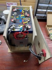
Hi @HRTKD. It's been a while but I'm finally nearly done with my first pack. I have a couple of questions regarding cables within the battery. Here's some background...Make sure your cables are the same length. Positive cable on battery A the same length as the positive cable on battery B. Same with the negative cables. The positive and negative cables don't have to be the same. Positives can be 18" and negative can be 12". That's OK. Positive of 12" on battery A and positive of 20" on battery B is no good.
I used 6 gauge welding wire for the negative cables between the pack main negative to the B- on the BMS (these two are 11" long). The same gauge cable is used from P- on the BMS to the box cover terminal (these two are 12" long).
Question: Do those two sets of cables need to be the same length? I realized when I was done that I didn't need the extra inch on the P- side so I could make them the same if that's necessary. I plan to replicate the configuration and lengths for the other three packs I will build next.
The pack main positive is coming from the left rear of the box (I haven't made that cable yet). I have a couple of questions on that cable.
Question: Does this cable gauge need to match the combined negative cables? I think two 6 gauge wires is equivalent to a 3 gauge? So is it okay to use 4 gauge or 2 gauge from the pack main positive to the terminal on the box cover? Or, should that match the 2/0 that I plan to use between all the boxes to the rest of the system?
Anything wrong with the way I'm doing this so far?
Thanks!
Attachments
Last edited:
3 gauge is indeed equivalent to two 6 gauge cables. The webpage below is a good calculator for that:
The cables on either side of the BMS do not need to be the same length. Neither does the 3 gauge cable on the positive side need to be the same length as the negative cables. Since 3 awg doesn't exist, or at the very least is difficult to come by, use 2 gauge. My wire gauge calculator says that 2 awg is good for about 200 amps over a 3' round trip distance.
Since you have multiple batteries you need to make sure all the negatives are the same length and then all the positives are the same length.
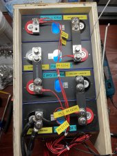
On Pack 1, Cell 1, it looks like you might have a ring terminal under the bigger cable on the negative post. It's hard to tell from the picture and the washer that is on the stud. On that same terminal, it looks like the cable lugs are torn. That's not good. I'm guessing that your crimping tool did that.
The cables on either side of the BMS do not need to be the same length. Neither does the 3 gauge cable on the positive side need to be the same length as the negative cables. Since 3 awg doesn't exist, or at the very least is difficult to come by, use 2 gauge. My wire gauge calculator says that 2 awg is good for about 200 amps over a 3' round trip distance.
Since you have multiple batteries you need to make sure all the negatives are the same length and then all the positives are the same length.
On Pack 1, Cell 1, it looks like you might have a ring terminal under the bigger cable on the negative post. It's hard to tell from the picture and the washer that is on the stud. On that same terminal, it looks like the cable lugs are torn. That's not good. I'm guessing that your crimping tool did that.
Thanks very much. I'll double check that ring terminal but I'm pretty sure I have all of them on top of the lugs and bars. I will also take a closer look at those lugs. Those were my first crimps with the new hydraulic tool so maybe I did have it too far up on the lug. I'll redo them. Really appreciate all of your advice throughout this process!3 gauge is indeed equivalent to two 6 gauge cables. The webpage below is a good calculator for that:
The cables on either side of the BMS do not need to be the same length. Neither does the 3 gauge cable on the positive side need to be the same length as the negative cables. Since 3 awg doesn't exist, or at the very least is difficult to come by, use 2 gauge. My wire gauge calculator says that 2 awg is good for about 200 amps over a 3' round trip distance.
Since you have multiple batteries you need to make sure all the negatives are the same length and then all the positives are the same length.
On Pack 1, Cell 1, it looks like you might have a ring terminal under the bigger cable on the negative post. It's hard to tell from the picture and the washer that is on the stud. On that same terminal, it looks like the cable lugs are torn. That's not good. I'm guessing that your crimping tool did that.
I will also take a closer look at those lugs. Those were my first crimps with the new hydraulic tool so maybe I did have it too far up on the lug. I'll redo them.
If your heat shrink tubing had been 1/4" longer I would have never spotted that.
")
Similar threads
- Replies
- 2
- Views
- 198
- Replies
- 18
- Views
- 671
- Replies
- 16
- Views
- 753
- Replies
- 16
- Views
- 516