diy solar

diy solar

18kpv w/two PowerPro Startup & Communication - HELP (resolved)

Goin'Solar

New Member
Joined
Aug 26, 2023
Messages
57
Location
West Coast
This weekend I installed my new 18kpv system with 2 PowerPro batteries. Got everything wired up, went through the (poorly described) start-up process -turned on the batteries, set the battery comms protocol to RS485, P01-EG4, switched on the Battery breakers on the 18k and the system sprang to life... sorta.

The first issue was no communication with battery. Shut down everything in reverse order and checked the communication protocol. It was correct as above. Did some googling and found a post where someone said try other comms... That didn't work so I switched back to RS485, P01-EG4. Started up and shut down a couple times- never went beyond turning on the battery breaker and now the inverter won't even turn on. Batteries show 55% state of charge.

Going to call customer service to see if I can get any help, but wanted to ask for any help or ideas here while I wait for them to open.
 
Thanks! I will try the shortly when I can get back out to the system.

Interesting that she says it has to be set to CAN/LUX when the manual states RS485/EG4
 
Thanks! I will try the shortly when I can get back out to the system.

Interesting that she says it has to be set to CAN/LUX when the manual states RS485/EG4
the "LUX" part of can/lux makes sense, since the eg4 18kpv is built by luxpowertek
 
Change to lead acid if you can't get the comms working, your units should then run. Check 50/60hz setting too if no grid on input.
 
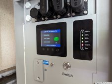
So I updated to CAN/LUX, but still having the issue with the inverter not turning back on. When I flip on the BATTERY breakers on the inverter, the batteries both make a clicking sound and the red ALARM light on the BMS display comes on.
 
So I updated to CAN/LUX, but still having the issue with the inverter not turning back on. When I flip on the BATTERY breakers on the inverter, the batteries both make a clicking sound and the red ALARM light on the BMS display comes on.


Turn everything off.

Turn the battery breaker on the inverter tot he on position.
Then turn on the breakers for the batteries themselves. This enables a pre-charge circuit, to power up the capacitors in the inverter.

Then turn on the power to the inverter.

If you are turning on the batteries before the main "battery" breaker on the inverter, you're not using the pre-charge resistor.. so the batteries see the capacitor as a dead short, and goes into an error/protection mode.
I don't know how long it will be before I get my order. I need to make sure I can find this when I do.
 
I don't know how long it will be before I get my order. I need to make sure I can find this when I do.

At the top right of the post, is a little ribbon looking thing. It allows you to save the post.

Screenshot 2023-11-05 at 2.46.00 PM.png
 
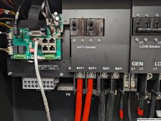
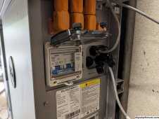
PXL_20231105_193502475.MP.jpgPXL_20231105_193536717.MP.jpgPXL_20231105_193701890.jpgTurn everything off.

Turn the battery breaker on the inverter tot he on position.
Then turn on the breakers for the batteries themselves. This enables a pre-charge circuit, to power up the capacitors in the inverter.

Then turn on the power to the inverter.

If you are turning on the batteries before the main "battery" breaker on the inverter, you're not using the pre-charge resistor.. so the batteries see the capacitor as a dead short, and goes into an error/protection mode.
That makes sense.
I tried what you said and still causing ALARM on the battery
Turned on inverter Bat+ breaker, then the battery's breaker, then the BMS power and got alarm. Also tried Bat+, then BMS, then battery's breaker and also got alarm.

Is there any other way to pre-charge the capacitor? This seems like the logical reason for the inverter not starting up after it had already started a few times. No wiring had been changed.

*For some reason my attached pics went to the quote of the previous post.
 
Last edited:
That makes sense.
I tried what you said and still causing ALARM on the battery
Turned on inverter Bat+ breaker, then the battery's breaker, then the BMS power and got alarm. Also tried Bat+, then BMS, then battery's breaker and also got alarm.

Is there any other way to pre-charge the capacitor? This seems like the logical reason for the inverter not starting up after it had already started a few times. No wiring had been changed.

*For some reason my attached pics went to the quote of the previous post.
You can precharge with a resistor, a #2 pencil sharpened on both ends, some 12v incandescent light bulbs wired in series, even a really long length of wire will work.
I use a resistor with a pigtail on one end and jump the switch / breaker (go from battery + to inverter +).
Don't panic if you get a small spark when you first make the connection.
 
Alarm always on? short circuit. Manual says disconnect the power cables, and check the cables. Please don’t hurt yourself I want to hear what the final resolution is.
 

Attachments

  • IMG_4147.png
    IMG_4147.png
    273.1 KB · Views: 10
Please don’t hurt yourself I want to hear what the final resolution is.
Haha! Thank you. All turned out well. The cable connections were all ok. What I didn't have connected yet were the Solar Panels. After I connected those, I turned the main switch on the side of the inverter to the ON position thinking it MAY be able to charge the capacitor. It may or may not have, but it did allow me to turn everything on and get the batteries working.

I can also confirm that the batteries are communicating in CAN/LUX.

Now to get the programming done here. Might have to wait until next weekend now to finish, but thanks all for the help. I'll add to this as I do more.
 

Attachments

  • 16992237446005946424170138908243.jpg
    16992237446005946424170138908243.jpg
    692.3 KB · Views: 22
  • 16992237811667311245603007792685.jpg
    16992237811667311245603007792685.jpg
    742.4 KB · Views: 22
Well, I guess it didn't charge the capacitor after all. As soon as I flipped the BAT+ Breaker, the batteries went into Alarm mode again.

I tried the pencil method and it turned the inverter on for a second, but the pencil started smoking and I shut it down. After I reconnected the battery cables, the batteries went back into Alarm status.
You do not need to precharge anything, something else is going on.
 
Well, I guess it didn't charge the capacitor after all. As soon as I flipped the BAT+ Breaker, the batteries went into Alarm mode again.

I tried the pencil method and it turned the inverter on for a second, but the pencil started smoking and I shut it down. After I reconnected the battery cables, the batteries went back into Alarm status.
Pencil shouldn't smoke. Are you sure all connections are correct, all polarity is correct? Sounds like something else is wrong.
 
You do not need to precharge anything, something else is going on.
I've double and triple checked all of my connections and everything seems to be as it should. The grid, load and generator are shut off/disconnected on the other end. There's no voltage on the grid load or generator lines. The load breaker is turned off. There is no continuity anywhere that it should not be.

Also, the first couple of times that I turned it on it worked fine. I was turning it on and off because I was trying to get the battery communication working. The only wires that have been added or changed are the PV inputs, but it started malfunctioning before I added those.

I'm open to any suggestions as to what to check next.
 

Attachments

  • PXL_20231105_235147279.jpg
    PXL_20231105_235147279.jpg
    714.2 KB · Views: 35
  • PXL_20231105_235230825.MP.jpg
    PXL_20231105_235230825.MP.jpg
    543.4 KB · Views: 25
  • PXL_20231105_235245481.jpg
    PXL_20231105_235245481.jpg
    700.2 KB · Views: 23
  • PXL_20231105_235257361.jpg
    PXL_20231105_235257361.jpg
    626.6 KB · Views: 32
  • PXL_20231105_235310051.jpg
    PXL_20231105_235310051.jpg
    887.2 KB · Views: 33
Seems like every time I’ve called SS the first thing they do is get me to update my firmware. Only thing I see different in yours vs. mine is I have a green communications cable. Which on the older unit have caused problems. You could only hook one battery up and then the other to isolate which one is giving you a problem. Or swap batteries to see if that fixes it.
 
Last edited:
Seems like every time I’ve called SS the first thing they do is get me to update my firmware. Only thing I see different in yours vs. mine is I have a blue communications cable. Which on the older unit have caused problems. You could only hook one battery up and then the other to isolate which ones getting your problem. Or swap batteries to see if that fixes it.
Firmware will have to be a next-weekend project. Sun is down here now and so I can't power it on. Work will take me away from my home in the hills where this is being installed. There were a couple of green data cables in with my kit as well, but it seemed that the grey ones were labeled for the 2 battery system.

I did try with only 1 battery powered on (the master) and it did the same thing. I don't think I'll transfer everything over to the other battery since you have to remove the conduit box to make the battery terminal connections. Whoever the engineer was that designed that should be fired.
 
Sorry it was green, I got this from the manual. It says it’s the battery to inverter communication cable.
 

Attachments

  • IMG_4148.png
    IMG_4148.png
    178.7 KB · Views: 14
Last edited:
Back
Top