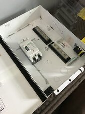
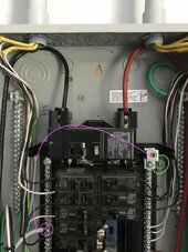
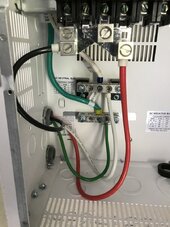
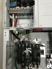
@dougbert How do I configure without the N-G bond? I have the Neutral wire from its busbar going to AC out. Is that correct? The white wire is connected to the AC Load out and then down the neutral busbar (where it was installed from the factory) Is this what you are saying?
yes, your 2 pictures of wiring look good
I have the full PDP and my pictures are crowded - lots more wiring in it - so they won't help
you system is fairly simple since no grid
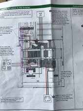
The wiring diagram shows the path in pink. The middle area between the black (Line 1) and Red (Line 2) is the N. The bottom portion of the neutral busbar was prewired at the factory.
let me echo your configuration so I am on the same page
1) transfer switch that toggles your main load panel between generator and the XW. Only one will be powering the loads
2) Transfer switch ONLY switches L1 and L2. Neutral is COMMON throughout the system
3) Ground is COMMON through out the system
4) N-G bond is only in the main panel. No bond in generator
Wire neutral from the XW through the PDP to transfer switch AND neutral from main panel to transfer switch. same with neutral from generator inlet plug to transfer switch
Ground do the same way, generator inlet, main panel and XW grounds all are connected to transfer switch
Generator L1 and L2 to one of the LINE sides of the transfer switch (top or bottom)
XW L1 and L2 to the other LINE side of the transfer switch
there are other topologies (wiring patterns) that will accomplish the same thing
if there are other features not mentioned, that could alter the design