


You are using an out of date browser. It may not display this or other websites correctly.
You should upgrade or use an alternative browser.
You should upgrade or use an alternative browser.
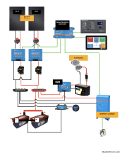
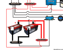
Does this schematic look right?
- Thread starter xavpil
- Start date
MaikaiLifeDIY
Solar Enthusiast
It looks accurate to me. Only question I might have is the disconnect for the mppt to the +/- block might be unnecessary, unless you’re thinking you need a way to de energize them on both sides so you could replace them without turning off the system.
I would also suggest to connect your smart shunt to your cerbo so you can see you batteries SOC remotely instead of only with the guage.
I would also suggest to connect your smart shunt to your cerbo so you can see you batteries SOC remotely instead of only with the guage.
MaikaiLifeDIY
Solar Enthusiast
I would also say you don’t need 2 charge controllers, you’re under 150v and 45amps either in a series or parallel wiring of your panels.
Thanks so much for the feedback. I’ll fix as you mentionedIt looks accurate to me. Only question I might have is the disconnect for the mppt to the +/- block might be unnecessary, unless you’re thinking you need a way to de energize them on both sides so you could replace them without turning off the system.
I would also suggest to connect your smart shunt to your cerbo so you can see you batteries SOC remotely instead of only with the guage.
Some people say that if one MPPT goes down at least I am still able to create some energy… I’ll be on a boat, offshore. What do you thinkI would also say you don’t need 2 charge controllers, you’re under 150v and 45amps either in a series or parallel wiring of your panels.
Some people say that if one MPPT goes down at least I am still able to create some energy… I’ll be on a boat, offshore. What do you think
If using 2 MPPT (for redundancy) suggest wire each MPPT directly to bus bars and not daisy chain them. Also suggest using same bus bars for batteries.
Zapper77
Renaissance Man
- Joined
- Jul 23, 2022
- Messages
- 2,341
High voltage PV switch vs the low voltage switch.For my sailboat, 800 W (2x400w)
I don't worry yet about the specs of each item.
Thx friends!
firs off thx!If using 2 MPPT (for redundancy) suggest wire each MPPT directly to bus bars and not daisy chain them. Also suggest using same bus bars for batteries.
what do you mean by "same bus bar for batteries"? Isn't it what I have already?
sorry, what do you mean exactly? the switch between panels and MPPT?High voltage PV switch vs the low voltage switch.
Zapper77
Renaissance Man
- Joined
- Jul 23, 2022
- Messages
- 2,341
Those DC switches are high amperage low voltage.sorry, what do you mean exactly? the switch between panels and MPPT?

They don't have the travel range, speed or arc suppression to safely disconnect higher voltage. (I see that the panels are only 50v but it would be better to use a PV isolation switch)
wow.... thx...Those DC switches are high amperage low voltage.
View attachment 181150
They don't have the travel range, speed or arc suppression to safely disconnect higher voltage. (I see that the panels are only 50v but it would be better to use a PV isolation switch)
What do you think about not using any switch as the recommendation I received previously?
Maybe I should have them closer to the batteries?
Zapper77
Renaissance Man
- Joined
- Jul 23, 2022
- Messages
- 2,341
You're on a boat. I would add a 12 amp inline fuse and keep the isolation switch.wow.... thx...
What do you think about not using any switch as the recommendation I received previously?
Maybe I should have them closer to the batteries?
Sorry, let me rephrase so it makes more sense.firs off thx!
what do you mean by "same bus bar for batteries"? Isn't it what I have already?
Edited:
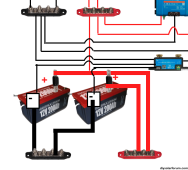
Use another set of bus bars for the batteries. The Wide RED and BLACK LINES between the batteries in the picture replace with a set of Positive and Negative bus bars. Then run equal length wires from each battery Pos & Neg to the corresponding battery bus bars. Finally run wires from the Battery bus bars to Pos bus bar already shown in the picture and the neg to the Victron battery monitor.
You could also run two equal length wires from both batteries to the Victron Battery Monitor for the negative and run two equal length wires from both batteries to the Positive of pictured Bus bar and that will work, but a dedicated set of bus bars for the batteries will be cleaner and allow additional batteries to be added in the future.
Hope that helps
Last edited:
wow.... thx...
What do you think about not using any switch as the recommendation I received previously?
Maybe I should have them closer to the batteries?
Agree with @Zapper77.
A switch is a good ideal. If there are problems it is nice to have a quick way to disconnect the solar panels from the Solar Charge Controller.
The link below should work.
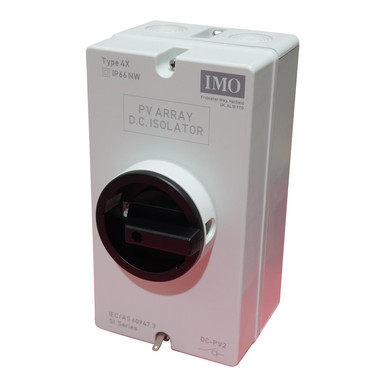
IMO DC Disconnect Rooftop Isolator Switch
IEC 60364-7-712, dc disconnect, imo, ul listed, DC AC, DC DISC
 signaturesolar.com
Closer?....Sorry, let me rephrase so it makes more sense.
Use another set of bus bars for the batteries. The Wide RED and BLACK LINES between the batteries in the picture replace with a set of Positive and Negative bus bars. Then run equal length wires from each battery Pos & Neg to the corresponding battery bus bars. Finally run wires from the Battery bus bars to Pos & Neg bus bars already shown in the picture.
You could also run two equal length wires from both batteries to the Victron Battery Monitor for the negative and run two equal length wires from both batteries to the Positive of pictured Bus bar and that will work, but a dedicated set of bus bars for the batteries will be cleaner and allow additional batteries to be added in the future.
Hope that helps
Attachments
Awesome!! ThxAgree with @Zapper77.
A switch is a good ideal. If there are problems it is nice to have a quick way to disconnect the solar panels from the Solar Charge Controller.
The link below should work.
IMO DC Disconnect Rooftop Isolator Switch
IEC 60364-7-712, dc disconnect, imo, ul listed, DC AC, DC DISC
Closer?....
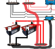
Yes closer, but sorry I had it worded incorrectly in my first response. Look at the edited response.
Finally run wires from the Battery bus bars to Pos bus bar already shown in the picture and the neg to the Victron battery monitor.
So just one wire from the positive battery bus bar to the existing pictured bus bar and one wire from the negative battery bus bar to the Victron Battery Monitor.
Attachments
oh man.... last shot and I'll leave you aloneYes closer, but sorry I had it worded incorrectly in my first response. Look at the edited response.
Finally run wires from the Battery bus bars to Pos bus bar already shown in the picture and the neg to the Victron battery monitor.
So just one wire from the positive battery bus bar to the existing pictured bus bar and one wire from the negative battery bus bar to the Victron Battery Monitor.
")
Attachments
Looks Good!oh man.... last shot and I'll leave you alone
Thx so much!Looks Good!
Similar threads
- Replies
- 7
- Views
- 553
- Replies
- 8
- Views
- 244
- Replies
- 9
- Views
- 817