diy solar

diy solar

Handy AC power meter.

Mattb4

Solar Wizard
Joined
Jul 15, 2022
Messages
4,221
Location
NW AR
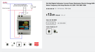
Been using these din rail power meters on my AIO's AC out to keep track of things. With all the information it always displays I do not have to cycle through the AIO's screens, run an app, log on to a PC or anything more than a glance. I went with the type that has the coil sensor rather than running a wire through the body of the meter as that seemed a better choice. There is some question if the power reading is apparent or real power but for my general use it does not matter. I like glancing at it when I have several loads up and seeing if I am within the AIO's safety margins. Bit like having a Kill-A-Watt-meter always connected.

I bought mine of Aliexpress but it can be found at Amazon and probably elsewhere. If you are just setting up your AIO you might consider putting in a din rail box (need a minimum of 2 slots) with clear face in a viewable location.
1690131633335.png
 

Attachments

  • P1010001.JPG
    P1010001.JPG
    303.6 KB · Views: 31
  • P1010002.JPG
    P1010002.JPG
    277 KB · Views: 31
I like that!
Maybe I’m dumb but it didn’t occur to me to find DIN meters- I bought multiple ‘panel’ meters with these functions but the dimensions are both inconsistent and have no standard panels to install them into. Looks messy.

I concur on external CT.
It would bother my head to pass 25A through that thing, never mind 100A. With a 12V system that will never see anything more than 3000W inverter 25A at 120V I suppose 25A would never be exceeded anyhow.
 
Last edited:
I have one of these that you pass the live conductor through a hole in the device , works fine as long as you measure on the live and not on the neutral. the only difference between the two is that one has an external CT and the other an internal CT.
 
Yeah, it's pretty amazing what they can cram into one of these for around $20.

I use these:


because they add two other functions:

elapsed time since last reset
(I like to know how long it took to run up that kWh)

temperature
(in Celsius, but I have gotten pretty good at doing ballpark conversions in my head)

Using them the same way - as an "at a glance" snapshot of what's going on on the AC side.

I mount them in Eagle Plastics 400-1561-GR project boxes after using the Dremel to make a cutout.
 

Attachments

  • KWH_meter.jpg
    KWH_meter.jpg
    119.7 KB · Views: 4
It occurs to me that although these AC meters are single phase you could still use it with a stacked inverter setup by using 2 to monitor each hot leg to watch how the loads are balancing (L1 and L2). That could be good to know and you would simply add the watts together.
 
Using them the same way - as an "at a glance" snapshot of what's going on on the AC side
Nice. Just need a 200A 12VDC model too lol
after using the Dremel to make a cutout
That’s the part that annoys me. Needs to be a snap in DIN standard like the rail mounts, car stereos, etc. It seems that none of these are made to any consistent standard my limited knowledge is aware of.
 
Nice. Just need a 200A 12VDC model too lol

That’s the part that annoys me. Needs to be a snap in DIN standard like the rail mounts, car stereos, etc. It seems that none of these are made to any consistent standard my limited knowledge is aware of.
It sure is frustrating that there are not more ready made enclosures for some of these things. My fabrication abilities is not always up to the task. My next project will involve me cutting out a proper size rectangle to fit a PV side shunt meter. And as you say they all have different dimensions to deal with which they often do not list.
 
In a split phase system if all you are looking for is total watt-hours without concern for balancing, a single CT can be used if you pass both hot conductors through it in OPPOSITE directions. The caveat is the unit has to think the system is 120 volts in order to make the math work out.

To recap, pass both hot conductors through the CT in opposite directions. Power the system from one leg and neutral for 120 volts. The total watt-hours displayed will be accurate but you won't see which leg used what.
 
Been using these din rail power meters on my AIO's AC out to keep track of things. With all the information it always displays I do not have to cycle through the AIO's screens, run an app, log on to a PC or anything more than a glance. I went with the type that has the coil sensor rather than running a wire through the body of the meter as that seemed a better choice. There is some question if the power reading is apparent or real power but for my general use it does not matter. I like glancing at it when I have several loads up and seeing if I am within the AIO's safety margins. Bit like having a Kill-A-Watt-meter always connected.

I bought mine of Aliexpress but it can be found at Amazon and probably elsewhere. If you are just setting up your AIO you might consider putting in a din rail box (need a minimum of 2 slots) with clear face in a viewable location.

View attachment 158966
I install these often for customers who want to keep track of tenants usage. Very simple to install and easy money.
 
There are plenty of small din rail closures on Amazon, I have used one to house the Watt meter and 2 CB's from my 2 inverters.
Yes, but the ‘loose’ snap-in panel mount meters are seemingly random-sized. That was my interest in seeing these DIN meters; for whatever reason when I bought mine it didn’t occur to me to see if DIN meters were available.

I’ve actually reordered a couple of the panel mount meters with the functions like the one posted here and the reorder from “amazonian outfitters” came in with a different size but similar-appearing housings which annoyed the OCD in me.
 
In a split phase system if all you are looking for is total watt-hours without concern for balancing, a single CT can be used if you pass both hot conductors through it in OPPOSITE directions. The caveat is the unit has to think the system is 120 volts in order to make the math work out.

To recap, pass both hot conductors through the CT in opposite directions. Power the system from one leg and neutral for 120 volts. The total watt-hours displayed will be accurate but you won't see which leg used what.
Clever. I am so used to the thought of using a current measuring device on only one leg at a time of a split phase your method of alternating direction is novel.
 
Clever. I am so used to the thought of using a current measuring device on only one leg at a time of a split phase your method of alternating direction is novel.
I learned it from the power company. They use it as a cost saving method. One CT is cheaper than two.
 
Nice. Just need a 200A 12VDC model too lol

...
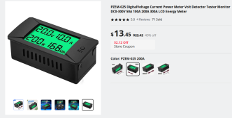
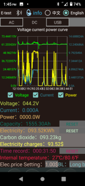
Might consider something like this. It is what I am going to use on my PV input. I am going to use a small 500ma 12v power supply to keep meter alive overnight. I have most of the pieces/parts but am awaiting the meter to arrive any day now.

1690466162052.png
 
Do these have directional capability? Could they be used to show ONLY what you send back to the utility?
 
Do these have directional capability? Could they be used to show ONLY what you send back to the utility?
Yes but no. You can usually utilize the data reporting of your ul1741 compliant device and see that, but with AC it’s gonna measure both directions. Otherwise measuring your PV input and calculating the advertised inefficiency out of that, then subtracting out your kWh that goes through your panel and the difference is roughly what you export. I hope I said that right.
 
The CT coil has no direction requirements. So I do not think it would serve as a grid upload measuring device. Here is the instruction sheet that comes with the AC meter.
 

Attachments

  • AC power meter.png
    AC power meter.png
    1.4 MB · Views: 4
CT coil has no direction requirements
Other than by circuit isolation or a comparative analyzer I don’t think any AC monitors can determine or differentiate “direction” because… 60Hz
 
Back
Top