CaliSunHarvester
Solar Enthusiast
Environment: 24V system
12 panels total 3.12kW pv
80A SCC
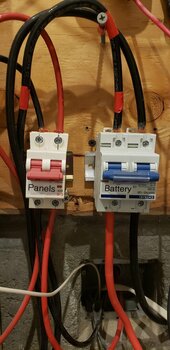
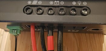
I was looking at my wiring with my new thermal imaging camera. I noticed that with peak sun (and we are just in March, mind you), the wires from the charge controller towards battery are very warm, both near the SCC, and at the DC breaker switch on both sides of the switch.
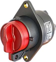
I also noticed that this switch is installed "backwards", which I will correct ASAP.
I measured twice.
At around 60A charge, the temperature was 97F (36C)
At around 75A charge, it shows a reading 133F (56C)
This wire from SCC via DC breaker to battery is:
Cerrowire-A Slipwire THHN/ THWN-2/MTW 4AWG (21.2mm2) GR11 SR VH-1 600V (UL) OR AWM 07/09/2023
I don't understand what this text means except 4AWG, the sqmm equivalent, 600V and - hopefully - the manufacturing date.
When I look up "awg 4 ampacity" various tables will qualify the result for a temperature.
e.g.
THHN/THWN-2 at 75 °C is 85 Amps.
THHN/THWN-2 at 90 °C is 95 Amps
since my wire does not have anything like 75C or 90C stamped on it, what does this refer to? Temperature of the environment? That would be very bad news, as this room is more like 20 Celsius.
Also, the wire temperature drops off within a few inches from my connections as visible in these 2 photos. Does this mean that *all* my connections are bad??? Every single one???


I think now that with ~80A charging, maybe I am too close to the wire limit (is it 85? or 95?) Especially if in summer I will get 80A for an extended number of hours of 80A. Right now it's probably just 1 hour. The SCC reports it as 82A actually. It could be 4 hours in August?
IIRC, this SCC cannot accept larger than AWG 4 wire.
12 panels total 3.12kW pv
80A SCC
I was looking at my wiring with my new thermal imaging camera. I noticed that with peak sun (and we are just in March, mind you), the wires from the charge controller towards battery are very warm, both near the SCC, and at the DC breaker switch on both sides of the switch.
I also noticed that this switch is installed "backwards", which I will correct ASAP.
I measured twice.
At around 60A charge, the temperature was 97F (36C)
At around 75A charge, it shows a reading 133F (56C)
This wire from SCC via DC breaker to battery is:
Cerrowire-A Slipwire THHN/ THWN-2/MTW 4AWG (21.2mm2) GR11 SR VH-1 600V (UL) OR AWM 07/09/2023
I don't understand what this text means except 4AWG, the sqmm equivalent, 600V and - hopefully - the manufacturing date.
When I look up "awg 4 ampacity" various tables will qualify the result for a temperature.
e.g.
THHN/THWN-2 at 75 °C is 85 Amps.
THHN/THWN-2 at 90 °C is 95 Amps
since my wire does not have anything like 75C or 90C stamped on it, what does this refer to? Temperature of the environment? That would be very bad news, as this room is more like 20 Celsius.
Also, the wire temperature drops off within a few inches from my connections as visible in these 2 photos. Does this mean that *all* my connections are bad??? Every single one???
I think now that with ~80A charging, maybe I am too close to the wire limit (is it 85? or 95?) Especially if in summer I will get 80A for an extended number of hours of 80A. Right now it's probably just 1 hour. The SCC reports it as 82A actually. It could be 4 hours in August?
IIRC, this SCC cannot accept larger than AWG 4 wire.
Last edited: