You are using an out of date browser. It may not display this or other websites correctly.
You should upgrade or use an alternative browser.
You should upgrade or use an alternative browser.
Lifepo4 terminal bars
- Thread starter Newenough
- Start date
Rider
Solar Addict
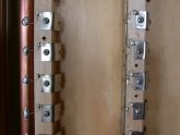
Something like this? Any home or electrical supply should have them.
https://www.lowes.com/pd/GE-7-in-Ground-Bar-Kit/3151469
https://www.lowes.com/pd/GE-7-in-Ground-Bar-Kit/3151469
Rider
Solar Addict
Probably not what you're looking for either...
Amazon.com: Pair of Voodoo Car Audio SAE Top Post (6) 1/0 & 4 Gauge BATTERY TERMINAL Pair: Gateway
Buy Pair of Voodoo Car Audio SAE Top Post (6) 1/0 & 4 Gauge BATTERY TERMINAL Pair: Battery Wiring & Terminals - Amazon.com ✓ FREE DELIVERY possible on eligible purchases
www.amazon.com
Rider
Solar Addict
Oh. Ok. Make your own. A piece of 1/2" copper pipe squashed flat and drilled out. That way you can make them exactly the length you need. Or a piece of flat stock steel/stainless.
offgriddle
"FOREVER BEGINNING"
The copper idea is great, copper conducts electricity well and easy to work with and affordable in small quantities and the only draw back is that copper has a tendency to corrode in damp and salty air environments especially when copper is connected to a different metal. Conductive electrical grease helps keeep corrosion down to a minimum. While stainless steel is also conductive, I hear that is not nearly as good at conducting as copper, iron, lead etc..Oh. Ok. Make your own. A piece of 1/2" copper pipe squashed flat and drilled out. That way you can make them exactly the length you need. Or a piece of flat stock steel/stainless.
b.james
New Member
Does not take long to squash a piece of 1/2 inch copper pipe flat and drill two holes in it then cut it separate with a small cut off wheel or a hacksaw if you must. Copper is the best conductor of electricity and stainless a poor one . Just get one right then use it as a template.
Stainless work hardens and is difficult to drill .
Stainless work hardens and is difficult to drill .
Yeah thats what I have been doing. Smashed $6 pipe from home depot, then drill press. Super simple and I have pushed 100's of amps for hours through them. Great method
I have been looking everywhere for a supplier of busbars for my banks and I cannot find one. I love the bus bars that come with the raw cell kits but I can never seem to source them. :/
TCgreg
Solar Enthusiast
- Joined
- Sep 21, 2019
- Messages
- 116
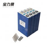
CALB makes an excellent busbar but they don't sell them without the battery cell. One design feature of their busbar is that it is flexible, made of multiple thin plates of copper and arched. LiFePO4 cells can expand when they get hot. This allows the busbar to give without placing stress on the battery terminals. CALB also states in their instructions that cells should be clamped together to minimize this expansion. Not sure about other similar cells made or marketed under different names. I see some that are delivered with flat plate busbars.
Here is something that looks similar to CALB. You would have to check the hole spacing although if they are like CALB busbars they are flexible to re-bend into different hole spacings within reason.
https://power.tenergy.com/lifepo4-130ah-battery-busbar-connector/
Here is something that looks similar to CALB. You would have to check the hole spacing although if they are like CALB busbars they are flexible to re-bend into different hole spacings within reason.
https://power.tenergy.com/lifepo4-130ah-battery-busbar-connector/
SCClockDr
Solar Enthusiast
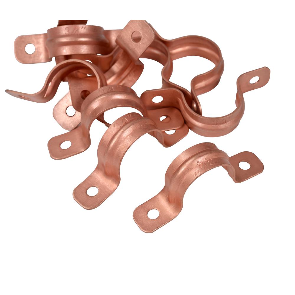
I just pulled some from my plumbing bin & they are magnetic. (Copper clad steel) There may be solid copper ones but a magnet will confirm no steel.
robaroni
New Member
- Joined
- Sep 30, 2019
- Messages
- 35
If you're on a budget you can use 1/2" copper pipe flattened out and drilled. You can even get creative with shrink tubing if you want. I did some prelim numbers and I think 1/2" 'L' ('L' is thick walled and carries more amps than 'M' pipe) pipe carries well over 100 amps with no problems.Sorry. Should have been more clear. This would be a battery terminal to terminal flat bar for series connection of lifepo4 cells.
Rob
Do we (me) really need to worry to much about having high amp connections? I currently have (5) 8s banks. Only growing from there. I charge at 60 amps .2C or roughly 12 amps at each bank (or .66 amps per cell). My nominal/continuous draw (in summer) is currently about 10 amps (.033c). Even if I quadrupled that draw (.165c) for startup of any appliances/AC its still very minimal per paralleled bank. So I would think just a solid copper #8 wire to each terminal would be more than enough wouldn't it? Or would there be a resistance issue even at 2 inches. Again, just trying to see the need for such heavy connections....
robaroni
New Member
- Joined
- Sep 30, 2019
- Messages
- 35
For point of reference. My bank is a 16S by 36P. Max charging is 60 or 80 amps, I forget which off hand. What I did when I built it was to use #24 wire as fusing between each pos battery terminal to the continuous neg rail of the next parallel 3.6v leg. Each 4S battery in the 48v system is ~12v (4S by 36P). Where all the pos #24 wires are tied to the pos outgoing rail I used 1/2 inch 'L' pipe. So essentially you have 36 times #24 wire as your current capacity base.Do we (me) really need to worry to much about having high amp connections? I currently have (5) 8s banks. Only growing from there. I charge at 60 amps .2C or roughly 12 amps at each bank (or .66 amps per cell). My nominal/continuous draw (in summer) is currently about 10 amps (.033c). Even if I quadrupled that draw (.165c) for startup of any appliances/AC its still very minimal per paralleled bank. So I would think just a solid copper #8 wire to each terminal would be more than enough wouldn't it? Or would there be a resistance issue even at 2 inches. Again, just trying to see the need for such heavy connections....
The reason I used a large copper rail is because of voltage drops in the bank when large loads like my well pump come on. What you don't want is a big drop during that current surge because it can drop your bank below inverter shut off voltages. (My inverters have a settable period that the voltage must be low before the inverter shuts off but many inverters don't have that.)
So in your design be aware of that, my case is a little different because I have 36 batteries in each leg and the length is almost 4 feet long. Try to keep your legs as short as possible, which I couldn't do.
I think AWG 8 is about 40 amps capacity which I think may be low, it's best to over engineer your design. My system usually runs between 5 and 10 amps to run my critical house loads but I still used AWG 2/0 to my inverters. I do notice a small drop under loads but it's not causing problems.


Last edited:
My bus bars are aluminum. Awg 2 from inverter to bus bars. So 5 legs 8s each. Will use Awg 8 from the bus bars to each bank and then 8 bare copper wire between each cell? So that theoretically would allow upto 40 amp draw on each bank for a max of 200 amp (40 x 5) which would exceed my inverters 40 / 120 surge capabilty be a huge margin. Anyone see a down side to using awg 8 bare copper between cells in this setup?
Last edited:
Keith_PDX
New Member
As most are aware aluminum is a good conductor (what a lot of wire uses these days) and it's very easy to work with. Why not buy some 1/4"×1" bar stock at ace or home depot and use it for the battery interconnect buss bar? I'd slot the holes a little for thermal expansion. My guess is that the terminals on these aluminium cased prismatic cells (pictured above) are aluminium?
 blog.se.com
Aluminium: Inherently good for bus bars - Schneider Electric Blog
Are aluminium bus bars really as conductive and rugged as copper? How do aluminium busbars handle heat? Inherent advantages of aluminium for bus bars?
Last edited:
Similar threads
- Replies
- 23
- Views
- 1K
- Replies
- 4
- Views
- 485
- Replies
- 25
- Views
- 2K
- Replies
- 4
- Views
- 340


