diy solar

diy solar

SUNGOLD 10KW 48V SPLIT PHASE SOLAR INVERTER

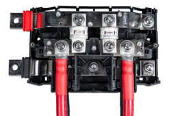
I'm fixing to install victron lynx bus bars that use the mega fuses. I want to put class T fuses in it. Does anyone know if they will fit into the lynx bus bar or not?
I doubt it. Everyone’s using the T Class holders. I’m not rebuilding to 2 t class holders on each of my back feeds right now. To hell with that! That’s 500+ fuse setup I hope you guys got the money and stones to build all that out but I’m kind of over working on this sucker https://diysolarforum.com/threads/t...-powerpro-batteries-and-the-serer-rack.68282/
 
Last edited:
You bought the mega fuses?

The other thread had a video where someone tested them.

One user summarized it up:

"After watching that video not sure anyone should be using mega fuses :unsure:"

Post in thread 'House burned down' https://diysolarforum.com/threads/house-burned-down.83098/post-1090686
Yeah but again that’s one documented case without decisive proof of area failure. Victrons not going to recommend those fuses without testing that shows a level of protection success, not saying t class ain’t better the AIC is better it’s the best solution, but I’m not writing off the megas as garbage. How many thousands of users with popped mega fuses DIDNT run to the forum to talk about how their fuse saved their house? All of them
 
Last edited:
the 2 videos are from a guy in Germany who tested Victron Mega fuses and iMAXXX Mega fuses. Unfortunately the videos are both in German only, fortunately I do speak and understand the language. Those videos are not related to the guy who had the fire.
Hard for me to tell what’s happening other than fuse go boom. Maybe one day I’ll rebuild with 2 t class in victrons for $340 for 4 batts and $160 in t class fuses, but I think I’m just going to run this now since it’s what I have. Since your building it out fresh it makes sense for you to t class it
 
Hard for me to tell what’s happening other than fuse go boom

yeah, that language barrier is an issue.

What's happening is.. that they did NOT go boom as expected.

The Victron fuse test starts at minute 9:50 and around minute 10:56 had been for 45 minutes at 176.5A and 90C warm (hot), yet not blown.

At minute 11:30 he replaces the wire with a thinner one, because he reasons that the thick wire acts as a heat sink.

With the thinner wire, more heat is generated and the fuse blew after 15 minutes in the test (minute 12:10 in the video)

The fuses that he tests were supposed to be blowing in 30 minutes, they are not "fast" fuses (??). He says early in the video that he bought these Victron fuses for 3 Euros, clearly your order is a different product (fast acting I guess).
It’s an interesting topic for sure, I know something else that’s important will be popping the hoods off these units and doing periodic inspection. Same problems I’ve experienced with EV and HV vehicle repair.. most damage could have been avoided had inspection of the equipment happened more often, many times… it was a leaker.

I don’t like that months earlier that user found a leaker
5536BD3A-8B86-4B98-B403-C63BC036D82E.jpeg
 
that months earlier

yes, periodic inspections incl tightening wires, still need to get that torque wrench/ driver

By the way it was "months earlier".. like in 30 months earlier. That user did regular inspections -- the last one had been 2 weeks prior to the fire.

The bulging battery was replaced in 2021.

I like to believe that prefabricated batteries like ours are safer, but, that's really just a belief or should I say, hope?
Lol I don’t think you should worry too much, again.. statistically the odds are on your side you WONT have a major melt down.. millions of batteries out there behaving right now.. 100’s of thousands of us running DIY / LiFePo4 setups and we’re fine. Always going to be a few of us that draw the short straw. Make the best judgments you can, mitigate risk where you can, early detection when possible.. keep rockin! No fear!
 
Last edited:
wait a moment!! You mean you will start periodic inspections of the inside of SGP equipment?

I see a big advantage with the wall mounted batteries in this moment. I think you could inspect them while in operation. Cannot imagine that with racks in a shelf.
Yes it’s easy to pop the hoods off
 
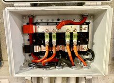
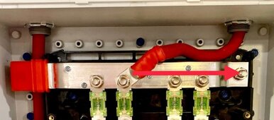
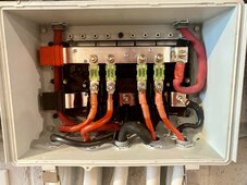
I plan to land that inverter feed on the end but I couldn’t make the bend, going to try to remove the line from conduit, rebuild end and try to land on last stud. Turned out it was a pita trying to bend that cable for the end stud landing @42OhmsPA
 
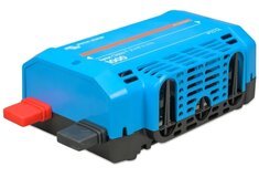
Ideally, the inverter is powered from the end of the bus bars and the batteries are tied to the bus bar with positive and negative in reverse positions.

Positive: 1 2 3 4 inverter
Negative: 4 3 2 1 inveter

The idea is to balance the current from each battery as much as possible and even small seemingly insignificant variations in resistance do have an effect.

Putting the inverter on a battery stud makes that battery dominant in the current flow. All the other batteries have to flow through that connection to get to the inverter except the battery on that stud.

Mike C.
That was tougher than I thought it’d be. That’s the best I could land it. I can tell current is being more evenly distributed D930FF73-6847-45C0-AE50-32281587AF9A.jpeg
 
Back
Top