You are using an out of date browser. It may not display this or other websites correctly.
You should upgrade or use an alternative browser.
You should upgrade or use an alternative browser.
Testing: Lead and lithium (LFP) battery banks in parallel
- Thread starter ShedLab!
- Start date
sunshine_eggo
Happy Breffast!
It will work, but it will behave much more like two separate batteries. Your means of parallel connection is going to be a big influence.
Above 52V LFP will carry almost all the load, and the lead will be a slight drain on the LFP. As the system voltage drops below 52V, the lead will start picking it up and progressively carry more. Not sure where, but somewhere in the 48-50V range, they will be roughly working together.
Above 52V LFP will carry almost all the load, and the lead will be a slight drain on the LFP. As the system voltage drops below 52V, the lead will start picking it up and progressively carry more. Not sure where, but somewhere in the 48-50V range, they will be roughly working together.
sunshine_eggo
Happy Breffast!
Sounds like a reasonable assessment. Parallel connection is with big wires as seen. Any thoughts on pros and cons?
Pro:
High cycle life for the LFP, and that's what you'll use most of the time. The lead is good "backup" in case you exhaust your LFP.
Lead is hardly cycled at all and should have a very long life.
Con:
Not worth doing unless you are upgrading an existing lead back and trying to get the most out of it?
IIRC, @Steve_S has a parallel lead/LFP setup.
Horsefly
Solar Wizard
I would add (as others have heard from me elsewhere here) that most but not all AGMs will want both a higher absorption voltage and a much longer absorption time than LFP. If that is the case, you probably will be doing a disservice to one or the other. AGMs really need to be fully charged at the right voltage and long enough that the current drops down to 1-2% of the 20C rating, else you are slowly ruining the AGMs.
From what I've seen, Steve has a 2-bank switch and can switch back and forth between his lead acid and LFP banks. I think the switch supports running them in parallel, but I don't think that is how Steve uses it. I may be wrong, so hopefully Steve will chime in here.IIRC, @Steve_S has a parallel lead/LFP setup.
Steve_S
Offgrid Cabineer, N.E. Ontario, Canada
I run either one or the other but not both simulatneously. I have tried for discharhing and teh differentials weren't too pleasant. I tested while charging 75A+ to both and that worked, to a point. Simply put, apply KISS and use one type at a time. I also change my SCC & Inverter profiles accordingly as well.
Given the relative fragility of, say, 12V LFP modules in 24V and 48V applications, do you see value in a lead string as a snubber/buffer and/or overall robustness enhancement? FETs are fragile... And, frankly, won't the lead also provide lower cost storage kWh?
Pro:
High cycle life for the LFP, and that's what you'll use most of the time. The lead is good "backup" in case you exhaust your LFP.
Lead is hardly cycled at all and should have a very long life.
Con:
Not worth doing unless you are upgrading an existing lead back and trying to get the most out of it?
IIRC, @Steve_S has a parallel lead/LFP setup.
sunshine_eggo
Happy Breffast!
Given the relative fragility of, say, 12V LFP modules in 24V and 48V applications, do you see value in a lead string as a snubber/buffer and/or overall robustness enhancement? FETs are fragile... And, frankly, won't the lead also provide lower cost storage kWh?
I don't agree with the premise.
Won't the LFP BMS discontinue/block charge when the battery is full regardless of how high the AGM ABS CV voltage is set to?
I would add (as others have heard from me elsewhere here) that most but not all AGMs will want both a higher absorption voltage and a much longer absorption time than LFP. If that is the case, you probably will be doing a disservice to one or the other. AGMs really need to be fully charged at the right voltage and long enough that the current drops down to 1-2% of the 20C rating, else you are slowly ruining the AGMs.
From what I've seen, Steve has a 2-bank switch and can switch back and forth between his lead acid and LFP banks. I think the switch supports running them in parallel, but I don't think that is how Steve uses it. I may be wrong, so hopefully Steve will chime in here.
I don't agree with the premise.
Why? It's not obviously unreasonable. It's not inconceivable to over voltage the blocking FETs with the inductance in cable runs etc. I've done it in fact.
sunshine_eggo
Happy Breffast!
Why? It's not obviously unreasonable. It's not inconceivable to over voltage the blocking FETs with the inductance in cable runs etc. I've done it in fact.
You aren't describing "relative fragility." You're describing mistakes.
Horsefly
Solar Wizard
The concept of a BMS blocking / LVD / HVD / over-current disconnect is as a last-resort protection device. You don't use it as a normal course of managing your battery bank. That's not what a BMS is for.Won't the LFP BMS discontinue/block charge when the battery is full regardless of how high the AGM ABS CV voltage is set to?
What your saying is akin to saying you want to pop your circuit breakers several times a day just to know you got to the current level you wanted.
The concept of a BMS blocking / LVD / HVD / over-current disconnect is as a last-resort protection device. You don't use it as a normal course of managing your battery bank. That's not what a BMS is for.
What your saying is akin to saying you want to pop your circuit breakers several times a day just to know you got to the current level you wanted.
A charge controller uses FET switches to block excessive solar from charging the battery. The internal BMS does the same thing - and from what I gather - at relatively conservative cell voltages. Circuit breakers are electro/thermal/mechanical devices carefully engineered to serve as occasional protection. What is your specific concern with using the BMS FET terminate charge? In fact this maybe happening much more than people realize.
Circuit breakers also don't self reset.
You aren't describing "relative fragility." You're describing mistakes.
Actually, I'm describing common and foreseeable use cases. I wouldn't even classify it as foreseeable misuse.
Horsefly
Solar Wizard
I'm saying that if you use a BMS as it is intended and the BMS causes a disconnect, it should be an indication to you that you have something to investigate and fix. If you just say "oh well, I'll just let the BMS take care of that issue" then you will inevitably grow to just ignore when the BMS tries to save you and your battery, since it may just be doing what you intended it to do every day.
Do what you want. It's your money (and your house, and your fire, etc.).
Do what you want. It's your money (and your house, and your fire, etc.).
Thx for the responses and fair points. To clarify - this is a short experiment/exploration/thought exercise. Not a permanent installation and certainly not an endorsement to do such things!
Existing batteries aside it should be possible to properly engineer / develop a 12V modular BMS that can serve, also, as the primary charge regulation device over wide range of system CV voltages and series module configurations. Including 'equalize' voltages up to 16, 32, 64V etc. The necessary hardware is there by virtue of the established BMS architectures. It's also somewhat difficult to understand the limitations of existing LFP 12V FET based BMS equipped batteries in this respect. They 'should' work without issue - even at equalize voltages. However, if the modules aren't intentionally designed for this then, of course, results may be unpredictable. Although my test worked perfectly and, in principle, it's a reasonable technical solution.
I should also mention that with 4 12V LFP batteries in series and conservative CV voltages of, say 56V, it's likely the end of charge will in fact be determined by high cell voltage cut-off (HVCD) of one of the internal BMS modules. It's unlikely the 16 series LFP cells will be balanced enough to prevent this. Common 12V LFP modules wired in series are also not sell-balancing so this will only get worse over time. All that to say that HVCD-based 'charge complete' can be happening more often than users realize - especially when there is no visual or audible indication, it's self resetting and the overall impact is benign.
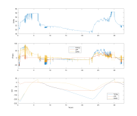
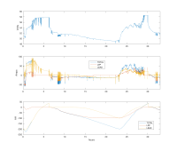
Beyond that there is some question about how the currents inherently share between two battery banks during charge and discharge. I have now collected this data for realz from the experimental system. It's pretty interesting. There is more 'washing' back and forth of charge current between the LEAD and LFP than one might imagine as the load and the sun vary.
Last edited:
Lots of interesting things going on here.
Initial conditions:
-Approximately 10am
-LEAD battery down 220AH
-LFP battery full
-LFP directly paralleled to the LEAD bank.
Notes:
charged by solar
discharged by a residential load
LFP bank blocks charging when full
AH counts above zero when charging but resets to zero when discharging begins again thus indicating the amount of 'overcharge'.
Any thoughts / observations?

Last edited:
Discharge Observations:
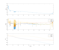
- at hour 7 LPF discharging into the LEAD a small amount
- at hour 9 a large intermittent load is initially supported by the lead bank but then the LFP bank replaces this discharged energy by charging the LEAD bank with charge replacement currents up to 20A.
- from hour 7 to 13 there is a net discharge from the LFP bank into the LEAD bank. It's not much but it's 'wasted' LFP capacity as it's not available to the load. Given enough time the LFP may significantly discharge into the lead bank at a low float-like current.
-most of the high load peaks are supplied by the LEAD bank throughout the entire discharge of the 100 AH LFP bank this illustrating the lower inherent internal resistance of the large(er) LEAD bank.
-generally the LFP discharges first 1st the LEAD discharges 2nd. The transition, in this case, is interestingly symmetrical.
-a failed/shorted discharge FET switch may allow cells to be over discharged - even down past zero V and into the negative voltages! I tested this and briefly discharged one of these LFP modules to -2V or so a couple of days ago (yes, I know you should never go below 10V...). Fortunately it seems to still work w/o obvious issue - but all information suggest this is not what you want to do to cells on a regular basis. This circumstance can easily happen with a small amout of imbalance between the 12V modules and a failed switch. BTW these failed FET switches can be really hard to notice and they can fail surprisingly easily in 48V system. 'i.e. they are relatively fragile'. I've experienced this personally and Bill Prowse has a good video of toasting a Renogy battery this way. The cheap charger gets singled out as the culprit but the fact is that it's relatively easy to create over voltage on the FETS when the try to interrupt any charging source or load that features a significant inductance - which the battery cables themselves can also add.
2nd Charge Observations
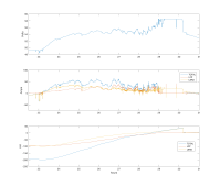
-initially the LEAD bank receives most but not all of the charge current.
-generally, the larger LEAD bank recharges 'first' first but the charge current much more shared and less sequenced than on discharge.
-in this case both the LEAD and LFP finish charging near the same time - although it's hard to say exactly when LEAD is finished due to the 'overcharge' required.
-you can see one of the LFP BMS modules interrupt the LFP bank charge current, at the right time, when the LFP bank is full thus preventing exposing the LFP bank to the 58V absorption voltage.
-a failed/shorted charge FET switch may expose cells to excessively high charge voltages - but this could be the case with almost CV charge voltage depending on how imbalanced the 12V modules are - even with the lowest suggest CV voltages for LFP like <=54V. Looks like some form of cell voltage-based HVCD is inherently required to interrupt the charge current unless the cells are all perfectly balanced - which they often won't be. Especially with individual series 12V modules that are not self-balancing.
Summary thoughts:
To implement 12V LFP modules optimally in a generalized 48V series configuration (i.e. not paralleled with lead) they may need the following features:
-Bulletproof internal FET disconnect switches that don't/won't/can't fail shorted.
-Internal FET disconnect switches that can serve as primary end of charge / discharge regulators. Many chargers out there are poorly regulated / calibrated and a timely end of charge termination based on any series cell reaching max voltage is important for LFP longevity. Many ‘loads’ out there also don’t have low voltage cut-out features.
-12V modules that have a self balancing feature so they don't drift apart over time when connected in series.
-Low temperature charging capability/protections/limits (including coordinated heating which does not imbalance series module SOCs - i.e. that never uses internal stored battery energy for self-heating or otherwise creates any deviation in the identical cell current of the modules in series)
Does this exist?

- at hour 7 LPF discharging into the LEAD a small amount
- at hour 9 a large intermittent load is initially supported by the lead bank but then the LFP bank replaces this discharged energy by charging the LEAD bank with charge replacement currents up to 20A.
- from hour 7 to 13 there is a net discharge from the LFP bank into the LEAD bank. It's not much but it's 'wasted' LFP capacity as it's not available to the load. Given enough time the LFP may significantly discharge into the lead bank at a low float-like current.
-most of the high load peaks are supplied by the LEAD bank throughout the entire discharge of the 100 AH LFP bank this illustrating the lower inherent internal resistance of the large(er) LEAD bank.
-generally the LFP discharges first 1st the LEAD discharges 2nd. The transition, in this case, is interestingly symmetrical.
-a failed/shorted discharge FET switch may allow cells to be over discharged - even down past zero V and into the negative voltages! I tested this and briefly discharged one of these LFP modules to -2V or so a couple of days ago (yes, I know you should never go below 10V...). Fortunately it seems to still work w/o obvious issue - but all information suggest this is not what you want to do to cells on a regular basis. This circumstance can easily happen with a small amout of imbalance between the 12V modules and a failed switch. BTW these failed FET switches can be really hard to notice and they can fail surprisingly easily in 48V system. 'i.e. they are relatively fragile'. I've experienced this personally and Bill Prowse has a good video of toasting a Renogy battery this way. The cheap charger gets singled out as the culprit but the fact is that it's relatively easy to create over voltage on the FETS when the try to interrupt any charging source or load that features a significant inductance - which the battery cables themselves can also add.
2nd Charge Observations

-initially the LEAD bank receives most but not all of the charge current.
-generally, the larger LEAD bank recharges 'first' first but the charge current much more shared and less sequenced than on discharge.
-in this case both the LEAD and LFP finish charging near the same time - although it's hard to say exactly when LEAD is finished due to the 'overcharge' required.
-you can see one of the LFP BMS modules interrupt the LFP bank charge current, at the right time, when the LFP bank is full thus preventing exposing the LFP bank to the 58V absorption voltage.
-a failed/shorted charge FET switch may expose cells to excessively high charge voltages - but this could be the case with almost CV charge voltage depending on how imbalanced the 12V modules are - even with the lowest suggest CV voltages for LFP like <=54V. Looks like some form of cell voltage-based HVCD is inherently required to interrupt the charge current unless the cells are all perfectly balanced - which they often won't be. Especially with individual series 12V modules that are not self-balancing.
Summary thoughts:
To implement 12V LFP modules optimally in a generalized 48V series configuration (i.e. not paralleled with lead) they may need the following features:
-Bulletproof internal FET disconnect switches that don't/won't/can't fail shorted.
-Internal FET disconnect switches that can serve as primary end of charge / discharge regulators. Many chargers out there are poorly regulated / calibrated and a timely end of charge termination based on any series cell reaching max voltage is important for LFP longevity. Many ‘loads’ out there also don’t have low voltage cut-out features.
-12V modules that have a self balancing feature so they don't drift apart over time when connected in series.
-Low temperature charging capability/protections/limits (including coordinated heating which does not imbalance series module SOCs - i.e. that never uses internal stored battery energy for self-heating or otherwise creates any deviation in the identical cell current of the modules in series)
Does this exist?
Attachments
Last edited:
This is interesting.
A few questions: if I understand your conclusions correctly from my thoroughly non-specialized POV, you are saying that this is a good way to both improve the performance and extend the life of existing lead installations? If this is economically interesting given the installed base, are you saying it remains difficult to do with existing battery/management technology? So what are you proposing?
Also, more prosaically, how did you collect the data?
Similar threads
- Replies
- 18
- Views
- 723
- Replies
- 47
- Views
- 2K
- Replies
- 4
- Views
- 610
- Replies
- 6
- Views
- 535
- Replies
- 258
- Views
- 13K


