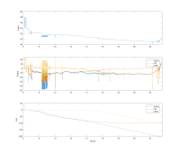
Discharge Observations:

- at hour 7 LPF discharging into the LEAD a small amount
- at hour 9 a large intermittent load is initially supported by the lead bank but then the LFP bank replaces this discharged energy by charging the LEAD bank with charge replacement currents up to 20A.
- from hour 7 to 13 there is a net discharge from the LFP bank into the LEAD bank. It's not much but it's 'wasted' LFP capacity as it's not available to the load. Given enough time the LFP may significantly discharge into the lead bank at a low float-like current.
-most of the high load peaks are supplied by the LEAD bank throughout the entire discharge of the 100 AH LFP bank this illustrating the lower inherent internal resistance of the large(er) LEAD bank.
-generally the LFP discharges first 1st the LEAD discharges 2nd. The transition, in this case, is interestingly symmetrical.
-a failed/shorted discharge FET switch may allow cells to be over discharged - even down past zero V and into the negative voltages! I tested this and briefly discharged one of these LFP modules to -2V or so a couple of days ago (yes, I know you should never go below 10V...). Fortunately it seems to still work w/o obvious issue - but all information suggest this is not what you want to do to cells on a regular basis. This circumstance can easily happen with a small amout of imbalance between the 12V modules and a failed switch. BTW these failed FET switches can be really hard to notice and they can fail surprisingly easily in 48V system. 'i.e. they are relatively fragile'. I've experienced this personally and Bill Prowse has a good video of toasting a Renogy battery this way. The cheap charger gets singled out as the culprit but the fact is that it's relatively easy to create over voltage on the FETS when the try to interrupt any charging source or load that features a significant inductance - which the battery cables themselves can also add.
2nd Charge Observations

-initially the LEAD bank receives most but not all of the charge current.
-generally, the larger LEAD bank recharges 'first' first but the charge current much more shared and less sequenced than on discharge.
-in this case both the LEAD and LFP finish charging near the same time - although it's hard to say exactly when LEAD is finished due to the 'overcharge' required.
-you can see one of the LFP BMS modules interrupt the LFP bank charge current, at the right time, when the LFP bank is full thus preventing exposing the LFP bank to the 58V absorption voltage.
-a failed/shorted charge FET switch may expose cells to excessively high charge voltages - but this could be the case with almost CV charge voltage depending on how imbalanced the 12V modules are - even with the lowest suggest CV voltages for LFP like <=54V. Looks like some form of cell voltage-based HVCD is
inherently required to interrupt the charge current unless the cells are all perfectly balanced - which they often won't be. Especially with individual series 12V modules that are not self-balancing.
Summary thoughts:
To implement 12V LFP modules optimally in a generalized 48V series configuration (i.e. not paralleled with lead) they may need the following features:
-Bulletproof internal FET disconnect switches that don't/won't/can't fail shorted.
-Internal FET disconnect switches that can
serve as primary end of charge / discharge regulators. Many chargers out there are poorly regulated / calibrated and a timely end of charge termination based on any series cell reaching max voltage is important for LFP longevity. Many ‘loads’ out there also don’t have low voltage cut-out features.
-12V modules that have a self balancing feature so they don't drift apart over time
when connected in series.
-Low temperature charging capability/protections/limits (including coordinated heating which
does not imbalance series module SOCs - i.e. that never uses internal stored battery energy for self-heating or otherwise creates any deviation in the identical cell current of the modules in series)
Does this exist?