diy solar

diy solar

Top Balancing "How to"

Was thinking of a simple method of balancing the new cells. Wire all cells in parallel, but with a 12V incandescent bulb in series with each cell. Would eliminate having to manually charge each battery to a similar voltage. Any flaw with my hypothesis?
I am not sure you need the bulbs.

 
Consider a resistor (or bulb) to bleed to similar voltage, wait until difference gets low before shorting together.
 
Was thinking of a simple method of balancing the new cells. Wire all cells in parallel, but with a 12V incandescent bulb in series with each cell. Would eliminate having to manually charge each battery to a similar voltage. Any flaw with my hypothesis?

There are only TWO places parallelling cells can achieve balance. Full and empty for top and bottom balances, respectively. Bottom balance is essentially worthless in a power system unless you plan to discharge it to empty every day and NEVER fully charge it - the opposite of how we use these systems.

Use the top balancing guide or a legit 2A+ active balancer.
 
I am not sure you need the bulbs.

Wills’ video and PDF does nothing to dispute my hypothesis. In fact, Will claims you do not need an active balancer.

At a minimum the bulb will eliminate the pre-charge step. If the benchtop power supply is low amperage, might as well leave the bulbs in place while top balancing. In theory if a bad cell shorts, the voltage difference will light the lamp.
 
Last edited:
Wills’ video and PDF does nothing to dispute my hypothesis. In fact, Will claims you do not need an active balancer.

Will's experience is not representative of the experience of MANY forum members. Legit active balancers make initial top balance and maintaining top balance easy.

The quality of Will's cells seems to be notably higher than what most forum members get. Expecting the same results Will gets is a bit deluded.

At a minimum the bulb will eliminate the pre-charge step.

I honestly don't even know what you mean by this. What is the pre-charge step? Do you mean building the battery with BMS installed and doing the initial charge to BMS cut-off? If so, that step is the most important step in accelerating the process. because you're passing the same current through all cells rather than dividing the current between parallel cells. Charging 10A on 16S is 16X faster than 10A on 16P.

If the benchtop power supply is low amperage, might as well leave the bulbs in place while top balancing.

How will bubs... which consume amps... help if the power supply is low amperage.

In theory if a bad cell shorts, the voltage difference will light the lamp.

Finally, I think I have it... Are you proposing to connect cells in parallel using bulbs instead of bus bars? If so, I don't see any useful purpose in that.

Even at low current, they have higher resistance than bus bars and will increase the needed Wh to charge the pack.
 
At a minimum the bulb will eliminate the pre-charge step. If the benchtop power supply is low amperage, might as well leave the bulbs in place while top balancing. In theory if a bad cell shorts, the voltage difference will light the lamp.

"Precharge", I think you mean charge to similar voltage before connecting in parallel. Which probably means something if some cells are near 100 SoC (above knee of curve) but others are below. If all below knee, I would test with the light bulb and see how close voltage comes. Calculate V/0.00025 ohms to see if surge current is a concern.

Some people have completed parallel top balancing, then when using battery found SoC differed between cells. One was low. Going back to charge that one alone to 3.65V fixed the issue. I blamed it on high resistance contact, so during charging that cell lagged.

If you deliberately add resistance in series with cells while charging, I think they will lag, take far longer to drift up to same SoC.

Finally, I think I have it... Are you proposing to connect cells in parallel using bulbs instead of bus bars? If so, I don't see any useful purpose in that.

Even at low current, they have higher resistance than bus bars and will increase the needed Wh to charge the pack.

Not Wh, I don't think, unless charge current is high enough to burn significant watts in the bulb.
But h (hours) definitely.
 
"Precharge", I think you mean charge to similar voltage before connecting in parallel. Which probably means something if some cells are near 100 SoC (above knee of curve) but others are below. If all below knee, I would test with the light bulb and see how close voltage comes. Calculate V/0.00025 ohms to see if surge current is a concern.

Some people have completed parallel top balancing, then when using battery found SoC differed between cells. One was low. Going back to charge that one alone to 3.65V fixed the issue. I blamed it on high resistance contact, so during charging that cell lagged.

If you deliberately add resistance in series with cells while charging, I think they will lag, take far longer to drift up to same SoC.

Not Wh, I don't think, unless charge current is high enough to burn significant watts in the bulb.
But h (hours) definitely.

If you apply a given amps at a given voltage for more hours, isn't that more Wh? :p
 
New half of a battery. So I put them into a pack and swapped it for the old one.

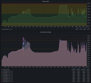
This is the top balance of the new 8S pack. On the left last night with the Multiplus battery charger and careful manipulation of the absorb voltage and charge current and ... on the right is the sun with my MPPT limiter automating that process. It looks like the automation did a much better job than I did with VEConfig!

Heltec 5A balancer. JK BMS - balancing disabled. As of 10am the loads came online. The MPPT limiter is still triggering on some cell delta at the top end, but it looks balanced enough to me.

1688569331532.png
 
Sorry if this has been covered, so much to read through, so probably has been.

Top balanced 16 304ah batteries at 3.65v. When it got down to .1amp, checked batteries, they showed 3.65v. Waited a little while, checked, showed 3.67v, still at .1 amps. Dropped the charger to 3.64v, and it stopped charging, showed zero amps. So, disconnected the charger, checked, they all showed 3.65 amps. Let them sit overnight, and this morning they all show 3.627v. Is this normal?

Also, batteries are Eve, IR: 0.2m ohm, 320-326 Ah, they all started at 3.292v.
 
Last edited:
Top balanced 16 304ah batteries at 3.65v. When it got down to .1amp, checked batteries, they showed 3.65v. Waited a little while, checked, showed 3.67v, still at .1 amps. Dropped the charger to 3.64v, and it stopped charging, showed zero amps. So, disconnected the charger, checked, they all showed 3.65 amps. Let them sit overnight, and this morning they all show 3.627v. Is this normal?

LFP is like lead acid. It must be charged to an elevated voltage to attain full charge. It is very common for voltage to drop over time. Given the extremely low current and 3.65V charge voltage, your cells likely have a pervasive "surface charge" on them where residual unusable charge keeps the cell voltages elevated. A bigger drop than you are seeing is more typical of cells in normal use, but this isn't uncommon after a balance charge to such low current.

Please refer to the cell datasheet. It likely says that the cell is fully charged at 3.65V AND 0.05C. In this case, that's 15A, i.e., once the cell hits 3.65V WITH 15A going into it, it's FULL. Any additional input does not yield meaningful usable capacity. By charging 16 304Ah cells in parallel, that's 4864Ah ... 0.05C is 243A, so assuming all cells shared current equally, they were full when they hit 3.65V and 243A. Of course, they likely don't share it equally, and nobody is using a 243A power supply. So, when your 10A power supply showed 10A with the cells measured at 3.65V, they were already full. Anything additional was essentially unusable charge.
Thanks for the reply
My charger didn't behave like you describe, never showed full amps (10 max), but instead stayed on voltage (showed the set voltage the whole time). So instead of showing being on amps and charging full amps and watching the voltage rise, it stayed on voltage and watched the amps drop. Don't think I ever saw higher than 7 amps.

This is likely due to the quality or lack thereof of your charge leads. One of the first items in the guide is a discussion on the need to construct higher quality leads. The losses in your cabling resulted in the charger "seeing" a voltage higher than the cells thus reducing the current. Even higher quality leads will see a reduction in current near the end of the charge.
 
This is likely due to the quality or lack thereof of your charge leads. One of the first items in the guide is a discussion on the need to construct higher quality leads. The losses in your cabling resulted in the charger "seeing" a voltage higher than the cells thus reducing the current. Even higher quality leads will see a reduction in current near the end of the charge.
Thanks again. This unit was advertised as having heavy duty leads, and they seemed bigger than normal, but I will make new ones.
 
Other possible explanations are high contact resistance (people here sometimes have one cell lagging the others), or cells were so close to 100% the power supply was CC from the beginning.

The test would be DMM between power supply and cell terminal itself.
 
Was thinking of a simple method of balancing the new cells. Wire all cells in parallel, but with a 12V incandescent bulb in series with each cell. Would eliminate having to manually charge each battery to a similar voltage. Any flaw with my hypothesis?
Once you wire in parallel, the cells can share unlimited power between them. That is why they need to be close before putting in parallel. What do you hope to accomplish with the bulb?

Not possible to simultaneously wire in parallel and series the same cells. You end up with a short.
 
Last edited:
Back
Top