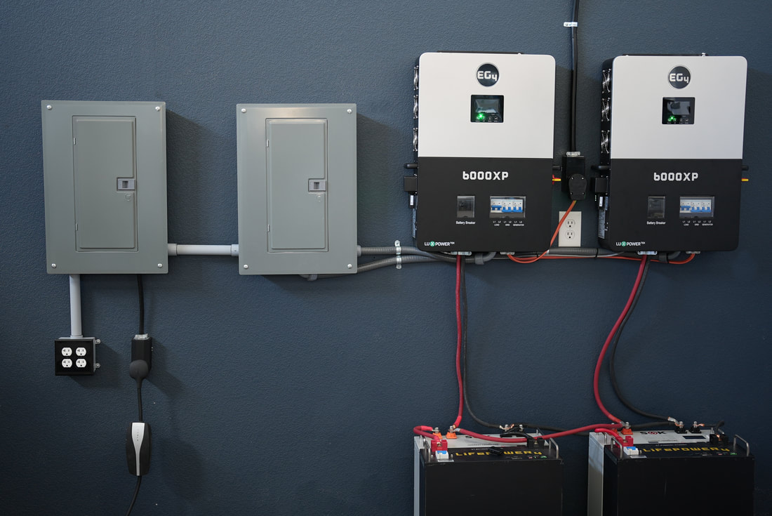
Our current home has two 200 Amp main panels fed from grid.
I am considering doing an "off-grid" setup based on Will's 'Complete DIY 48V Offgrid Solar Power System' design here:
 Some deviations I plan:
 reliancecontrols.com
If possible my plan would be to have the first EG4 6500 120V output to go to the single pole breakers in the first Transfer Switch & the second EG4 6500 120V output to go to the single pole breakers in the second Transfer Switch & both outputs combined to provide the 240v to the double pole 240V breakers in both Transfer Switches.
reliancecontrols.com
If possible my plan would be to have the first EG4 6500 120V output to go to the single pole breakers in the first Transfer Switch & the second EG4 6500 120V output to go to the single pole breakers in the second Transfer Switch & both outputs combined to provide the 240v to the double pole 240V breakers in both Transfer Switches.
I believe my primary south facing roof has room for approximately 18 of these 410 panels if placed in 3 rows of 6 with each panel rated at 410W & 37.12V Volts Open Circuit (VOC):
 signaturesolar.com
Overall I think the 18 panels gives an estimated total array of 7380 Watts & array of 684 VOC assuming each panel's W & VOC is summed additively. If I broke up the 18 panels into 2 strings of 9 panels then each of the 2 strings would be 3690 Watts & 342 VOC with the same additive assumption.
signaturesolar.com
Overall I think the 18 panels gives an estimated total array of 7380 Watts & array of 684 VOC assuming each panel's W & VOC is summed additively. If I broke up the 18 panels into 2 strings of 9 panels then each of the 2 strings would be 3690 Watts & 342 VOC with the same additive assumption.
Each EG4 6500 is spec'ed to handle 8000 Watts with a Max PV Array Open Circuit of 500VDC & have 2 MPPT each able to handle 18A per MPPT.
Question 1: Would it be safe/advisable to feed one string of 9 panels into a single MPPT on each EG4 6500 or should I break them into smaller strings (4 strings)?
Question 2: If the above is OK, would it be safe/advisable to feed both strings of 9 panels into both MPPTs on a single EG4 6500?
My 2nd question stems from the single EG4 6500 max 8000 Watts specification exceeding my planned 7380 Watts but I am concerned that IF VOCs of each panel are summed additively the 684 VOC may be too much for a single EG4 6500's 500VDC max PV Array Open Circuit... My hope is that each string's 342 VOC does not count additively toward the 500VDC max or that I am calculating total VOC wrong...
In part the reason I ask the 2nd question is because in a true grid down situation my only critical 240V needs can be manually turned on/off during the day (my small septic pump & my small pool pump & maybe a water heater as a dump load) & I was thinking that I could maybe put my most critical 120V loads on just one EG4 6500 and shut down the other EG4 6500 (after manually switching off all 240V breakers in both transfer switches & all 120V breakers in the 2nd transfer switch). My hope would be being able to cut the steady state &/or idle draw in half yet still be able to pull/manage my full 7380W of solar & manage batteries from just one EG4 6500 (& only start the 2nd EG4 6500 when I have excess solar/battery and then do 240V loads).
Note that I do realize that this would limit the amount of 240V load I could run as one leg from the primary would be carrying the most critical 120V loads but I think I can manage that in an emergency... If I find that just isn't doable then I could maybe look into adding a split phase transformer to handle the imbalance of phase loads...
Edit: If the above array VOC is too much for a single EG4 6500 & I really want to be able to do most of what I need on just 1 EG4 6500 I could look to drop the total array to 12 panels which would be 4920 Watts & 456 VOC total or if separated into two 6 panel strings would be 2460 Watts & 228 VOC per string.
I am considering doing an "off-grid" setup based on Will's 'Complete DIY 48V Offgrid Solar Power System' design here:
48V Offgrid Solar Power System
If you wish to build the ultimate offgrid solar power system, look no further: All-in-one units make setup a breeze. Each unit has it's own Inverter, MPPT, Transfer Switch and Battery Charger. Budget...
www.mobile-solarpower.com
- -Want grid AC fed into both EG4 6500's to be able to power more than solar &/or batteries would otherwise be able to (when grid is available);
- -Plan to feed Load Center Panel into two 50 Amp A510C Pro/Tran 2 Transfer Switches that transfer desired circuits from my two 200 Amp main panels (mix of double-pole & single pole circuits); More info about this Transfer Switch is at this URL:
Top-Quality Transfer Switch Kit | Reliance Controls
We provide top-quality generator transfer and safety switch, generator transfer panel, power transfer switch for generator, and house generator transfer switch.
I believe my primary south facing roof has room for approximately 18 of these 410 panels if placed in 3 rows of 6 with each panel rated at 410W & 37.12V Volts Open Circuit (VOC):
Solarever 410W Half-Cell Mono PERC Solar Panel (Black)
Signature Solar provides solar panels, off-grid solar systems, grid-tie, and hybrid systems. Quality solar inverters, bifacial solar panels, complete solar kits, solar batteries. Featuring brands such as EG4 Electronics with their solar battery, LifePower4 and EG4 LLifePower4 and EG4 LL
signaturesolar.com
Each EG4 6500 is spec'ed to handle 8000 Watts with a Max PV Array Open Circuit of 500VDC & have 2 MPPT each able to handle 18A per MPPT.
Question 1: Would it be safe/advisable to feed one string of 9 panels into a single MPPT on each EG4 6500 or should I break them into smaller strings (4 strings)?
Question 2: If the above is OK, would it be safe/advisable to feed both strings of 9 panels into both MPPTs on a single EG4 6500?
My 2nd question stems from the single EG4 6500 max 8000 Watts specification exceeding my planned 7380 Watts but I am concerned that IF VOCs of each panel are summed additively the 684 VOC may be too much for a single EG4 6500's 500VDC max PV Array Open Circuit... My hope is that each string's 342 VOC does not count additively toward the 500VDC max or that I am calculating total VOC wrong...
In part the reason I ask the 2nd question is because in a true grid down situation my only critical 240V needs can be manually turned on/off during the day (my small septic pump & my small pool pump & maybe a water heater as a dump load) & I was thinking that I could maybe put my most critical 120V loads on just one EG4 6500 and shut down the other EG4 6500 (after manually switching off all 240V breakers in both transfer switches & all 120V breakers in the 2nd transfer switch). My hope would be being able to cut the steady state &/or idle draw in half yet still be able to pull/manage my full 7380W of solar & manage batteries from just one EG4 6500 (& only start the 2nd EG4 6500 when I have excess solar/battery and then do 240V loads).
Note that I do realize that this would limit the amount of 240V load I could run as one leg from the primary would be carrying the most critical 120V loads but I think I can manage that in an emergency... If I find that just isn't doable then I could maybe look into adding a split phase transformer to handle the imbalance of phase loads...
Edit: If the above array VOC is too much for a single EG4 6500 & I really want to be able to do most of what I need on just 1 EG4 6500 I could look to drop the total array to 12 panels which would be 4920 Watts & 456 VOC total or if separated into two 6 panel strings would be 2460 Watts & 228 VOC per string.
Last edited: