diy solar

diy solar

XW pro optional ground?

Lake country

New Member
Joined
Nov 3, 2020
Messages
20
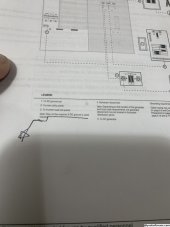
Does anyone know why on page 61 of the XW pro installation manual (ac grounding) it says you may not have to run a ground wire to your critical load panel if you are using dc grounding? This would be great for me because I have 3 wire feeder buried between my inverter and critical load panel.
 

Attachments

  • DE5BB123-31A4-40AF-91B8-A285E61D76A8.jpeg
    DE5BB123-31A4-40AF-91B8-A285E61D76A8.jpeg
    374.2 KB · Views: 11
Both your sub panel and XW need to be connected to ground. The connection doesn't need to go directly from the XW to the subpanel.

I've got both my subpanel and XW running separate grounds to the main panel and existing ground bus bar.

The XW doesn't do any funny business with the ground, so you just need to make sure everything has a ground and that you don't make a second neutral/ground bond.

This would be great for me because I have 3 wire feeder buried between my inverter and critical load panel.
3 + ground?
Or is your sub panel 120vac?

page 61 of the XW pro installation manual
The PDF version has something very different on page 61, can you post the full page? It's probably worth it for you to work from the most up to date PDF, not the old printed version shipped with the inverter.

Screenshot_20231203-093441.png
 
Thank you for the reply, do you have a link to the latest version you are looking at? All the ones I can find look like my book.

My feeder wire (ac out) is 4awg aluminum mobile home feeder wire it’s just L1, L2, and neutral.

I believe in my case the critical load panel needs to bond the neutral to ground or else it won’t trip the breaker during a fault condition in one of my critical loads.

My main reason for posting this is because I don’t want to bury a 4th line if I don’t have to.
 
Thank you for the reply, do you have a link to the latest version you are looking at? All the ones I can find look like my book.
I just downloaded it straight from their website.
My feeder wire (ac out) is 4awg aluminum mobile home feeder wire it’s just L1, L2, and neutral.
Was the originally the utility feeder?
I believe in my case the critical load panel needs to bond the neutral to ground or else it won’t trip the breaker during a fault condition in one of my critical loads.
The neutral ground bond should be a the first point of disconnect. Do you have a breaker at the utility meter? The neutral ground bond should be there.
My main reason for posting this is because I don’t want to bury a 4th line if I don’t have to.
Yup, I would too. But from the sound of it you may need to. Do you have a diagram of the entire set up? That would help better understanding.
 
Okay so I downloaded the same version you have, the diagram is on page 66. It says a grounding wire may not be needed if dc grounding is used. Thoughts on that?

the 3 wire feeder from the xw to my critical load panel is one that I buried a little over a year ago. I don't currently have the critical load panel purchased and wired in yet, just the feeder wire coming into the house next to the the house main panel.

There is a breaker on the main power box on the outside of the house as well as on the main house panel that is inside and the shop panel also has a breaker. I will attach a diagram showing the layout.Screenshot 2023-12-04 at 09-55-02 Untitled Visual Workspace for Innovation.png
 
Since the N-G bond is in the Main service entrance, the shop subpanel should NOT have a 2nd N-G bond. Although your drawing doesn't show how the shop panel is grounded but it should be.
 
That diagram is difficult or unworkable with that 3 wire feeder. There are cheater ways to bond the CLP but that would create two grounding systems in the main house which is a pretty major no no.

In fact both of the 3 wire feeders are problematic for the outbuilding back to the house route. Replacing either one alone wouldn't fix it.
 
Last edited:
Since the N-G bond is in the Main service entrance, the shop subpanel should NOT have a 2nd N-G bond. Although your drawing doesn't show how the shop panel is grounded but it should be.
The shop panel does have it's own earth ground and it was built before 2008.
 
My main concern is that the ground wire will trip the breaker during a classic fault condition, earth grounding the equipment is not a major concern of mine (enlighten me if it should be). I will ground the equipment to earth when I can. My current plan is to install the CLP next to the house panel, move critical circuits over (Including neutral wire, hot wire, ground wire) Then bond the neutral and ground in the clp so that if there is a fault condition in one of my critical appliances the breaker in the clp will trip.
 
That diagram is difficult or unworkable with that 3 wire feeder. There are cheater ways to bond the CLP but that would create two grounding systems in the main house which is a pretty major no no.

In fact both of the 3 wire feeders are problematic for the outbuilding back to the house route. Replacing either one alone wouldn't fix it.
What is the problem with having a second panel in the house that is fed with off grid power if the ground wire does what it's supposed to do (trip the breaker if there is a fault condition in your microwave for example).
 
I follow the logic and I would probably not be too scared of that system to use it. But as you know you're breaking a lot of rules that way.
 
What is the problem with having a second panel in the house that is fed with off grid power if the ground wire does what it's supposed to do (trip the breaker if there is a fault condition in your microwave for example).
Touch potentials I think. Two grounding systems doesn't reliably hold all metal at same potential so one hand on house panel dryer and other hand on inverter powered fridge are contacting separate grounding systems.

IF no open neutral faults I agree it should only be maybe up to 5v differential but it's lacking a lot of safety in case of an open neutral.

High conductivity contacts, fridge touching dryer, could open up a significant parallel path for all the panel's neutral current. I'm not actually sure if the risk there is very significant or not. I don't go that far off the code. It may be serious.
Appreciate the input, thank you. On another note, did you see that diagram from the Schneider install book that says the ground wire is optional if dc grounding is used? That seems odd to me, wondering what all that is about.
 
Appreciate the input, thank you. On another note, did you see that diagram from the Schneider install book that says the ground wire is optional if dc grounding is used? That seems odd to me, wondering what all that is about.
I did and I would ignore it. I think it just means it can use battery wire as an alternate path to the grounding system if they are bonded, and it wouldn't change the facts of the rest of the grounding scheme at hand here. That's my guess.
 
I did and I would ignore it. I think it just means it can use battery wire as an alternate path to the grounding system if they are bonded, and it wouldn't change the facts of the rest of the grounding scheme at hand here. That's my guess.
Yeah my thought was that it would maybe apply to the earth grounding aspect of the system, not the clearing faults aspect of the system.
 
Have a look at mistersandals neutral diagram here, mine is the same way:


I almost feel like there's some other possible tricks to get up to but I can't think of them yet.

Like what if you only connect L1/L2/G to XW in shop, and then L1/L2/N to CLP. And then CLP N and G bond to house main N and G.

I still gotta roll that around a bit in my head.
 
Last edited:
Would you be willing to run a ground wire from the service entrance to the shop panel?
Then you'd have everything bonded and ground the same N/G bond. That would mean you can piggy back the ground from your main panel to the critical loads panel.

This is about your safety not functioning of the breakers.

I almost feel like there's some other possible tricks to get up to but I can't think of them yet.

Like what if you only connect L1/L2/G to XW in shop, and then L1/L2/N to CLP. And then CLP N and G bond to house main N and G.
It wouldn't meet code and I'm sure there are other ways it isn't safe or could be made unsafe. But I think your right, you could (if the ground from the CLP to the shop is appropriately sized) remove the shop NG bond, run ground from the main panel, to the CLP, XW, then to the shop panel.
And run the XW/CLP neutral the other way around the loop XW to shop panel to service entrance to main to CLP.

In my opinion there's lots of good reasons not to do this. Run the missing ground wire(s)
 
to the CLP, XW, then to the shop panel.
I'm not picturing that connection or breaking the shop NG bond, I'm breaking it out into two grounding systems, with the XW neutral resident of the main house grounding system and the XW chassis grounded to the shop panel.

It's not legal and it's questionably sensible, but I don't think running extra grounds alongside these feeders is legal either, unless they are in conduit. If they're in conduit by all means fix everything up with 4 wire feeders all over.
 
There is no way I'm running another wire from my main to my shop, it was installed in 2001 and is under my deck and half my driveway and it was code when it was put in. As far as my safety vs functioning of the breakers, in my mind those are one in the same not opposing.
 
Back
Top