diy solar

diy solar

6000xp max voltage input...2 mppt's 17a/17a...do the inputs take up to 480v each?

Chio Antonius

New Member
Joined
Mar 13, 2024
Messages
9
Location
Landers
Hey just joined to ask about the6000xp input voltage. Since the inverter has two pv inputs and each handles 17a each does that also mean that I can put 400v into each input? or is that input 1 and input 2 combined total not to exceed 480v? So 225v per input?
Suggestions please. I've learned a lot doing this myself but don't want to fry equipment or make assumptions that lead to mistakes. I am new and this system is off grid. I have battery and 11kw diesel gen.

Equipment:
9kw of 30 panels:
39.25 Voc
9.77 Isc
How can I max both inputs out on the 6000xp?

I tried 26 panels
2 strings of 6 panels each -> combiner -> input 1
235.5 voc -> 192.9 vmpp
19.54 isc -> 18.66 imp
with the same going to input 2.
2 strings of 6 panels -> combiner -> input 2
Should be around 3.4kw each input, correct?

It didn't get cold enough to rise over voltage point. Now the temperature is warming up with no cold mornings.

I did 11 in series alone to one input and it seemed to put some good juice through. Can I do that to both inputs??

I am gonna use all the juice it makes
Only have enough room for 26 panels as of now but can eventually use all 30.
How can I utilize this machine to its full potential?

How can I get 8kw (4000w each) or the whole 9kw (4500w each)
and stay under 480v?
 
17A max usable per MPPT
25A max Isc per MPPT (over-panel limit)

480V is a NEVER exceed per MPPT. You don't go by how cold it got this winter. You go by the record cold temperature for your area, and you leave some headroom.

You say 26 panels, but I only count 24. For 26 panels:

6S2P on one MPPT
7S2P on the other MPPT

For all 30:

7S2P on one MPPT
8S2P on the other MPPT

All are well under the 480V limit for each MPPT.

11S is safe only if it NEVER EVER gets below 4°C.

I would stick with 10S as an upper limit.

The MPPT can't generate more than 4000W each, but putting more than 4000W on each MPPT (480Voc/25A Isc max) will allow each MPPT to produce 4000W for longer.
 
So it IS 480v limit per pv input !? That's the answer I was hoping for! Thank you.
When I make more room I'll try the 7 and 8 panel way to max out.

For now I do have 26 out there but have it hooked to 11 in series to one input to test that route. I would like to use the combiner boxes else where for future.

To clarify - 12 panels , 6 panels per string to combiner. That's what 6s2p means correct?

I'll check my records but the 11S is producing better than the other set ups.
The 11S produced more than the 6s2p did and more than the 7s2p. It was winter.
Another thing I though was odd, but I'll have to double check, was the 7s2p produced less than the 6s2p. I remember seeing the voltage a little higher on the line that was making less power. I'll double check and try each set up, isn't too hard to change wire connections.


Take away...please check my thought:
-7s2p & 8s2p would be the highest producing set up with a larger voltage head room? or at least I'm able to use all panels with little clipping. It should be just a tiny bit over 17a.
-10S each line is safe.
but
-I can put 11S to each input. I don't see 39F from mid-spring to late-fall.
-39F is common only at night and just as the sun rises during core winter months so I can disconnect one panel during winter to be safe.
thanks again.
 
This is my first forum experience. It is quite foreign to me...ha... and getting answers quick is a good time. Thanks
 
So it IS 480v limit per pv input !? That's the answer I was hoping for! Thank you.

Yes.

For now I do have 26 out there but have it hooked to 11 in series to one input to test that route. I would like to use the combiner boxes else where for future.

As long as it never gets below 4°C.

To clarify - 12 panels , 6 panels per string to combiner. That's what 6s2p means correct?

Yes.

I'll check my records but the 11S is producing better than the other set ups.
The 11S produced more than the 6s2p did and more than the 7s2p. It was winter.
Another thing I though was odd, but I'll have to double check, was the 7s2p produced less than the 6s2p. I remember seeing the voltage a little higher on the line that was making less power. I'll double check and try each set up, isn't too hard to change wire connections.

2P puts you slightly over the 17A limit, so you MIGHT lose 1.66/18.66A = 8.9% in near perfect conditions.

Are all panels facing the exact same direction?

Are any panels subject to ANY shade AT ALL at any time of day?

Take away...please check my thought:
-7s2p & 8s2p would be the highest producing set up with a larger voltage head room? or at least I'm able to use all panels with little clipping. It should be just a tiny bit over 17a.

Yes

-10S each line is safe.
but

No. Due to the below:

-I can put 11S to each input. I don't see 39F from mid-spring to late-fall.
-39F is common only at night and just as the sun rises during core winter months so I can disconnect one panel during winter to be safe.
thanks again.

Check daily charts of temperature. MOST of the time, it's coldest JUST before sunrise, not at night. LIGHT produces voltage, and even the initial kiss of sunlight on the panels can produce near full Voc, and that sunlight isn't sufficient to heat the cells to lower the voltage.

If you really get to -39°F, limit to 9S. 10S is only safe down to about -25°C

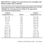
Please refer to the following NEC correction chart:


1710380310637.png

You need to allow at 25% margin. That means 480V/1.25 = 384V.

That's 9S max.

Things can work PERFECTLY until something doesn't. Don't push it. You don't fuck with MPPT Voc limits. Period.
 
I'm digging this forum and your responses!! thorough quote/response method!
So it so happens to be hitting 39F the next couple days on forecast. That is only right before and during sunrise which is when panels will get as kiss of sun. Which is when the 'fuck' would occur with Voc/mppt cooking, right?

I'm checking and the factor is 1.1 (40F to 32F)
I'm not in the high desert of a Russian tundra at -39F freezing my a$$ off.

480v/1.1 = 436v

392 voc for 10 of my panels.
78v of head room


I tried the math for coefficient # and I got 447v @ 32F) but that's where I'm a unsure, I have not been able to check my own math. If that is a good number or correct then 10 is safe because that is cold and won't get colder than that. I could disconnect during the cold season and reconnect when it's extremely unlikely to get below 70 here, even at dawn. I will play it safe though.

431 voc for 11 of my panels.
49v head space @ 32F a 54v increase is not good.
I want to check that increase at 39F...431v is lower than 436v

My math needs to be check and will be complete (temporarily).
You answered my main question of 480 each input...
I'm about ready to go out to my mount and tinker wires.

I have one wire overhead coming from Edison going to house. I screwed placement and the last 2 to 4 panels of the array get a thin line of shade that slowly goes across it in the early after noon for an hour or two I think. That could be the issue with the input imbalance.

You are crushing it and my brain is sizzling,, solar is almost as satisfying as cheese!
I am stoked with your responses eggo sun waffle!
 
22F is the coldest on record here ( so rare but not unlikely )
41.9F is average low Dec/Jan , wind chill can drop it

-Tomorrow 7am sunrise will be 45F but will feel like 36F.

10 panel pushing safety zone string?
11 panel stupid sizzle the inverter string? (not sure what the damage is when over voltage occurs)
9 panel play it safe string?

gonna drop it to 9 panels and hope to hear that 10 is legit for summer time or at least 5-6 months.
OH!!! spaced out on the original for a min... just go back to 6s2p & 7s2p with no issues like you said and eventually get to the 7s2p and 8s2p set up with no issues.
 
LOL....

you were using a hyphen as a bullet point. You might want to watch that in the future... :p

Wind chill does not affect panels, but it can contribute to their cooling. Picture a cold, partly cloudy day where cold winds cool the panels down while not in direct sunlight and then direct sun+cloud edging effects spike the voltage as the sun peeks around the clouds.

22°F needs a 14% margin, so 480/1.14 = 421V. 10S is good.
 
So it IS 480v limit per pv input !? That's the answer I was hoping for! Thank you.
When I make more room I'll try the 7 and 8 panel way to max out.

For now I do have 26 out there but have it hooked to 11 in series to one input to test that route. I would like to use the combiner boxes else where for future.

To clarify - 12 panels , 6 panels per string to combiner. That's what 6s2p means correct?

I'll check my records but the 11S is producing better than the other set ups.
The 11S produced more than the 6s2p did and more than the 7s2p. It was winter.
Another thing I though was odd, but I'll have to double check, was the 7s2p produced less than the 6s2p. I remember seeing the voltage a little higher on the line that was making less power. I'll double check and try each set up, isn't too hard to change wire connections.


Take away...please check my thought:
-7s2p & 8s2p would be the highest producing set up with a larger voltage head room? or at least I'm able to use all panels with little clipping. It should be just a tiny bit over 17a.
-10S each line is safe.
but
-I can put 11S to each input. I don't see 39F from mid-spring to late-fall.
-39F is common only at night and just as the sun rises during core winter months so I can disconnect one panel during winter to be safe.
thanks again.
480v limit per MPPT input on the 6000XP.
 
17A max usable per MPPT
25A max Isc per MPPT (over-panel limit)

480V is a NEVER exceed per MPPT. You don't go by how cold it got this winter. You go by the record cold temperature for your area, and you leave some headroom.

You say 26 panels, but I only count 24. For 26 panels:

6S2P on one MPPT
7S2P on the other MPPT

For all 30:

7S2P on one MPPT
8S2P on the other MPPT

All are well under the 480V limit for each MPPT.

11S is safe only if it NEVER EVER gets below 4°C.

I would stick with 10S as an upper limit.

The MPPT can't generate more than 4000W each, but putting more than 4000W on each MPPT (480Voc/25A Isc max) will allow each MPPT to produce 4000W for longer.
According to SignatureSolar Tech Support, today, "The manual states there are two separate PV circuits, one for each input. This means each input can handle up to 25A, but will only utilize up to 17A total." What does this mean, can it utilize 17A per 6000XP or per MPPT as you state above. I can get a straight answer to this question from SS. The manual helps none by listing the Imp as "17/17A". What!? Did somebody keyboard stutter?
 
According to SignatureSolar Tech Support, today, "The manual states there are two separate PV circuits, one for each input. This means each input can handle up to 25A, but will only utilize up to 17A total." What does this mean, can it utilize 17A per 6000XP or per MPPT as you state above. I can get a straight answer to this question from SS. The manual helps none by listing the Imp as "17/17A". What!? Did somebody keyboard stutter?

It's very simple.

An array has two values - max power current, Imp and short circuit current, Isc.

The Isc of your array must be UNDER 25A. Regardless of the array's Imp value, it will not draw more than 17A from the array.

It is common for people to put more array on the MPPT than it can handle for over-paneling purposes, like for more power on cloudy days, to produce peak output for longer periods in the middle of the day.

Example (made up numbers): Array with 24A Isc and 21.5A Imp. The array is allowed because the 24A is under 25A. While the array can produce 21.5A, the MPPT will only draw 17A, but it will draw 17A for as long as a 21.5A array will produce 17A, so rather than a bell curve profile of power every day, you will get a bell curve with a flat top where you produce max power for a few hours rather than just at noon.

17A/17A is just indicating the max usable on two MPPT, 17A each.

Is it now clear to you?
 
According to SignatureSolar Tech Support, today, "The manual states there are two separate PV circuits, one for each input. This means each input can handle up to 25A, but will only utilize up to 17A total." What does this mean, can it utilize 17A per 6000XP or per MPPT as you state above. I can get a straight answer to this question from SS. The manual helps none by listing the Imp as "17/17A". What!? Did somebody keyboard stutter?

Sunshine_eggo explains this very well. If you do have any more questions, feel free to reach out.
 
The Isc of your array must be UNDER 25A. Regardless of the array's Imp value, it will not draw more than 17A from the array.
Just curious.
Do you know why there is a max. Isc (25A) for the MPPT specified at all because the MPPT will anyway clip the current to it's max. usable current (17A)?

I'm using different AIO's with different MPPT specs, but the principle should be the same. I ask because I've double checked my PV panel production data over the last 30 days and found that my maximum Impp current on one string (4 panels in series, 15° tilt facing south on flat roof) was over the panel specifications.

These are the specs (BI-FACIAL BSM460M-72HBD):
STC (+3%): Isc=11.50A, Impp=10.86A
biacial gain 25%: Isc=14.03A, Impp=14.03A
Tcoeff Isc: +0.043%/°C
(STC with 1000W/m^2, cell temp 25°C)

For a couple of minutes (cloud edge effect?!) I was able to measure an Impp of 15.7A. The ambient temperature at this time was 38.5°C (Vmpp=138V).

When I take the 25% max. bi-facial gain and the Tcoeff ISC I would never reach 15.7A Impp (theoretically at 301°C cell temperature, which is impossible - I've researched that a max. of 100°C under hottest possible conditions should be the cell temperature limit). But even calculating with 100°C cell temperature, the Imppt would be at 14.5A and not 15.7A!

I assume that both the Isc and Impp would increase with the same percentage. Now I wonder what would happen under more extreme conditions? Here in our location we see usually 50°C ambient for a couple of days (official record was 53.3°C/128°F).

Calculate it the other way around, an irradiation of >1,100W/m^2 would have been required to explain my values (with 65°C cell temperature assumed).

I think the only possible explanation is a much higher irradiance than 1,000W/m^2 for a short time due to an extreme cloud edge effect (I've googled and found reported extreme values of 1,600 or even 2,000W/m^2 for some seconds). If the max. Isc would really be a hard limit which should not be exceeded, than this would be a big problem in my opinion.

Think about a hypothetical 6000XP example. You've done everything right and limit the max. Isc for a string to e.g. 22A under temperature coefficient consideration to not max it out. It works for days/month/years and suddenly you will see an extreme cloud edge effect with factor e.g. of 1,400W/m^2 and your string will have suddenly an (potential) Isc of 31A.

Now I ask myself some questions:
  • Why at all is a PV module max. Isc specified on some MPPT's if the MPPT is anyway limiting to the max. Imppt?
  • If an max Isc limit is really important, why do only a some MPPT's specify a max. Isc beside the max. Imppt (e.g. the EG4-6500EX does not specify it) and if not specified which value should/could be assumed if not specified?
    Maybe it's just because to protect the MPPT unit against wrong PV polarity? (I found such a hint e.g. in the Victron MPPT 450 model spec: "A higher short circuit current may damage the controller if PV array is connected in reverse polarity"). But on a different Victron e.g. MPPT 150/35 there is a different hint: "A PV array with a higher short circuit current may damage the controller").
  • Until now I assumed that the max. PV specification values could never be exceeded, but this seems to be wrong because you can't limit the increased irradiation in case of cloud edge events. So where are the limits which should used for calculations in real life and is there a potential danger for the equipment?
 
Just curious.
Do you know why there is a max. Isc (25A) for the MPPT specified at all because the MPPT will anyway clip the current to it's max. usable current (17A)?

I can tell you why Victron places a limit on it. Their MPPT have PV reverse polarity protection. This works by SHORTING the PV terminals together to force the array voltage to 0V. The contactor is rated for a given voltage and current. Beyond those specifications, the contactor may fail to operate or may weld itself closed and permanently damage the MPPT rendering it inoperative.

On any unit, there may be other fault protection features that may not work if too much current is present.

Taking the above description to a general concept, whatever the limitation, there are circuits or components that would fail if a limit is exceeded. I'm going to trust that the manufacturer knows more than I do, and I will respect those limits accordingly.
Ok, thanks. Your explenation about the protection mechanism limits makes totally sense.

Beside this, I can't imagine why an MPPT would be harmed by a higher possible Isc at usual operating, because the Isc will never be seen inside the MPPT (after the strings are already installed with the correct polarity).
 
Back
Top