diy solar

diy solar

My EG4 6500EX Exploded on restart!!!!!

Just wanted to provide a quick update. Other than long wait times when calling and some confusion as to how I would know if the return was approved after being received back, everyone I have talk to at SS has been very friendly and helpful. Long story short, both Inverters were returned and store credit granted. I then used that credit to purchase the 18K PV which should be arriving today. Thanks for everyone's feedback and help.
 
I will start another thread with the details, but let me just say WOW...the 18k PV is Awesome (yes there are some things you should be aware of, and different from the 6500's). I also want to thank @Markus_EG4. I did the commissioning on my own (which is not their standard practice) and when I ran into an issue and asked a question on the forum, he immediately jumped in (on the weekend) and helped resolve my issues. Again, more to come in a new thread, but right now I would say 9 out of 10 starts.....what a difference! Its in a whole new league and well worth the investment.
 
If you remove AC input from grid it takes a few seconds for inverter to recognize AC input has gone open circuit.

During this period the pass-through relay remains closed with inverter AC output showing on inverter AC input terminals and the inverter starts to drift off frequency and phase from grid which is not providing phase sync mastering for inverters.

Inverter will recognize when AC input is open when it drifts too far off frequency or it lacks getting phase corrections from AC input sinewave zero crossings for some period of time.

If you reapply AC input before pass-through relay has released, you will likely get a 'boom' due to inverter still connected via pass-through relay to AC input terminals and inverter is now out of AC phase with grid. It is like you applied grid to AC output of inverter, which is the error code you got.

Normal AC input connect process is with pass-through relay open, the inverter slowly syncs to AC input phase and voltage. After achieving AC input match it closes pass-through relay putting inverter output in parallel with AC input. AC input is phase and voltage master for inverter.

Whenever pass-through relay is closed, inverter is slave to AC input. Whenever pass-through relay is open the inverter is its own master.

If you are running inverters as series stacked 240/120vac configuration, they are slave to their respective L1 or L2 AC input phase when AC input is present.

When no AC input is present, one inverter becomes 180 deg phase reference master for other unit.

AC inputs for split phase should be fed via a double pole AC input breaker so both inverters get AC input simultaneously and simultaneously get disconnected from AC input when breaker is opened.

All this is also why you should not use an automatic transfer switch on AC input of inverter to switch between generator and grid. You must ensure inverter's pass-through relay is open before changing AC input source.
 
If you reapply AC input before pass-through relay has released, you will likely get a 'boom' due to inverter still connected via pass-through relay to AC input terminals and inverter is now out of AC phase with grid. It is like you applied grid to AC output of inverter, which is the error code you got.
That's a very important new information for me!

I didn't expect that the inverter can't handle a short timed AC-in grid connect/disconnect situation. In case when AC-in is permanently connected to the grid and the grid will have an outage with short on/off fluctuations (which happens sometimes), the AIO's would be in risk to "explode" because of that. In my opinion, this would be a dangerous design flaw!
AC inputs for split phase should be fed via a double pole AC input breaker so both inverters get AC input simultaneously and simultaneously get disconnected from AC input when breaker is opened.

All this is also why you should not use an automatic transfer switch on AC input of inverter to switch between generator and grid. You must ensure inverter's pass-through relay is open before changing AC input source.
Beside the (manual) double pole AC-in breakers (together with an AC-in main breaker) I also placed contactors to connect all AC-in's to the grid for all AIO's only in case AC-in (grid) is really required if batteries are nearly empty and no solar. I control the contactors via smart home rules depending on data getting from SolarAssistant via MQTT. It would be easy for me to implement a delay for this contactor rule to prevent the "boom" situation because of to fast AC-in switching.
What do you think would be a safe delay between disconnecting the AC-in from the grid before a new connecting may occur?

I only want to connect the AC-in to the grid when I really need it is to not use grid energy at all with typical usage (enough battery and solar). I found out that each AIO consumes about 50W from the grid (about half of it's idle consumption) if just connected to the grid even if not used! Because I'm running 6 of these EG4-6500EX in parallel, it would cost me 300W permanent grid usage without needing it (I may need the grid only about 3-5 days per year for maybe 1-3 hours on these days here in the desert and I don't want to waste >2,600kWh per year from the grid just to be connected to it).
 
It is common issue on all grid interactive inverters.

One of the toughest things for hybrid inverter to detect is an opening of AC input circuit. Voltage detection is of no use since with pass-through relay closed the inverter will present its AC output voltage on AC input terminals. It has to detect open AC input by AC input current or lack of AC phase sync mastering of inverter from AC input.

You can have a normal situation of zero AC input current so AC input current alone cannot be relied on and just zero AC input current situation will not cause inverter to release pass-through relay. One way for inverter to test for legitimate grid is to wiggle the inverter phasing a little which should push against the immovable grid phasing causing small detectable AC current from inverter as it tries to wiggle its phasing against grid phase.

Problem is the inverter, lacking a controlling master for phase sync will wander off frequency/phase. If you re-connect AC input too quickly before inverter recognizes loss of AC input in open circuit configuration and has not yet released its pass-through relay connection, there will be an AC phasing clash between AC input and inverter that will draw high surge current on inverter.

HF inverters are more vulnerable than LF inverters to this.

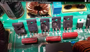
Worse case results for a HF inverter IGBT PWM output H-bridge transistors. Exploding IGBT's describes it pretty well.
HF inverter with blown PWM IGBT's.jpg
 
Last edited:
If you remove AC input from grid it takes a few seconds for inverter to recognize AC input has gone open circuit.

During this period the pass-through relay remains closed with inverter AC output showing on inverter AC input terminals and the inverter starts to drift off frequency and phase from grid which is not providing phase sync mastering for inverters.

Inverter will recognize when AC input is open when it drifts too far off frequency or it lacks getting phase corrections from AC input sinewave zero crossings for some period of time.

If you reapply AC input before pass-through relay has released, you will likely get a 'boom' due to inverter still connected via pass-through relay to AC input terminals and inverter is now out of AC phase with grid. It is like you applied grid to AC output of inverter, which is the error code you got.

Normal AC input connect process is with pass-through relay open, the inverter slowly syncs to AC input phase and voltage. After achieving AC input match it closes pass-through relay putting inverter output in parallel with AC input. AC input is phase and voltage master for inverter.

Whenever pass-through relay is closed, inverter is slave to AC input. Whenever pass-through relay is open the inverter is its own master.

If you are running inverters as series stacked 240/120vac configuration, they are slave to their respective L1 or L2 AC input phase when AC input is present.

When no AC input is present, one inverter becomes 180 deg phase reference master for other unit.

AC inputs for split phase should be fed via a double pole AC input breaker so both inverters get AC input simultaneously and simultaneously get disconnected from AC input when breaker is opened.

All this is also why you should not use an automatic transfer switch on AC input of inverter to switch between generator and grid. You must ensure inverter's pass-through relay is open before changing AC input source.
So let’s say your grid connection has various protection devices (reclosers or sectionalizing loop auto switches) such that gird can be lost for 1-2 seconds then be restored multiple times over the course of say 5 min? During a storm I can count the reclosings of my circuit knowing that if we hit that 4th time it’ll be lights out.

So basically these shouldn’t be used a UPS?
99.99% of the time anything happens to grid, it is collapse. Rarely if every does it go open circuit. Even if your utility pole transformer blows its HV primary side fuse from a critter getting across the HV insulator on top of pole transformer you usually share the secondary side of pole transformer with neighbors that will drag your grid down.

When grid collapses there is a momentary overload on inverter and in less than 4 milli-secs the inverter immediately releases pass-through relay. Grid collapse is usually not an instant voltage drop to zero and severity of voltage drop off rate depends on where in the sinewave cycle it drops.

Grid glitches are hard on the pass-through relay contacts though.
 
Last edited:
It is common issue on all grid interactive inverters.
HF inverters are more vulnerable than LF inverters to this.
What causes a HF inverter to be more vulnerable than a LF inverter to this? And what about a Schneider XW (or Outback) that is doing grid support? Wouldn't a LF inverter that can do zero export/grid support have the same susceptibility? Or do they function differently in terms of how they monitor the grid interaction? Or does the transformer play a part in "absorbing" the impact of the out-of-phase connection? (Although then that would still be hard on the transfer relays.)
 
On a LF inverter the PWM'g MOSFET's are at the battery side of large low frequency transformer so the high surge current is reduced by transformer losses.

On a HF inverter there is only the HF PWM L-C filter between IGBT PWM switching devices and AC input.

Setting zero export has nothing to do with it. Inverter output runs in parallel connection with AC input when pass-through relay is closed. Inverter initially needs pass-through relay to be open to allow it some time to sync to AC input before pass-through relay is closed.
 
On a LF inverter the PWM'g MOSFET's are at the battery side of large low frequency transformer so the high surge current is reduced by transformer losses.

On a HF inverter there is only the HF PWM L-C filter between IGBT PWM switching devices and AC input.
That makes sense.
Setting zero export has nothing to do with it. Inverter output runs in parallel connection with AC input when pass-through relay is closed. Inverter initially needs pass-through relay to be open to allow it some time to sync to AC input before pass-through relay is closed.
I would argue that it could play into it.

While the LF inverter is charging, it is drawing current and the instant the grid is disconnected, the power flow needs to reverse and the inverter would see that and open the transfer relays.

While the LF inverter is doing grid assist, it is staying locked to the frequency from the grid, but pushing just enough power to feed the loads, but avoid drawing from grid. Now if the grid is disconnected, it seems to me you would get the effect you described when you said this:
One of the toughest things for hybrid inverter to detect is an opening of AC input circuit. Voltage detection is of no use since with pass-through relay closed the inverter will present its AC output voltage on AC input terminals. It has to detect open AC input by AC input current or lack of AC phase sync mastering of inverter from AC input.

You can have a normal situation of zero AC input current so AC input current alone cannot be relied on and just zero AC input current situation will not cause inverter to release pass-through relay. One way for inverter to test for legitimate grid is to wiggle the inverter phasing a little which should push against the immovable grid phasing causing small detectable AC current from inverter as it tries to wiggle its phasing against grid phase.
But I do know that the Schneider XWs open their relays instantly when the grid input breaker is opened. It just seems to me that the whole part of sensing the grid being there or not would operate the same way between LF vs HF.
 
On a LF inverter the PWM'g MOSFET's are at the battery side of large low frequency transformer so the high surge current is reduced by transformer losses.

On a HF inverter there is only the HF PWM L-C filter between IGBT PWM switching devices and AC input.

Setting zero export has nothing to do with it. Inverter output runs in parallel connection with AC input when pass-through relay is closed. Inverter initially needs pass-through relay to be open to allow it some time to sync to AC input before pass-through relay is closed.
but this alone tells one that a HF inverter is not a good long term investment. the US has dropped to the level of a third world country on everything. during the fukashima event, we got most of our sticks and bricks house power from fukushima. we had 2 outages of about 3 minutes each, and then a rolling brownout program was put in place "in case the power created was not enough" in reality we had our power shut down 3 times in the first week. after that it was as stable as can be. in the US power goes down after a simple hurricane for weeks... people are standing in line to buy gas or diesel for their generator sets to keep their fat ass CPAPS running. 3rd World... nothing more. if you live in a third world country, which is what the US is at this point, albeit a very rich third world country you need reliability and HF inverters are not high on that scale.
 
Last edited:
While the LF inverter is doing grid assist, it is staying locked to the frequency from the grid, but pushing just enough power to feed the loads, but avoid drawing from grid. Now if the grid is disconnected, it seems to me you would get the effect you described when you said this:
If connected to grid, and inverter is not in standby mode, whether backfeeding, charging, or pass-through AC input to AC output, the inverter must be sync'd to AC input whenever pass-through relay is closed.

Even in standby mode, the controller pre-sync's to AC input so it knows how to active the inverter from standby, in phase sync with what the grid was before grid dropped out. This keeps AC output in proper sinewave phase progression, avoiding surge current that would happen from AC motor loads attached to AC output of inverter if there is a sudden AC phase shift discontinuity.
But I do know that the Schneider XWs open their relays instantly when the grid input breaker is opened. It just seems to me that the whole part of sensing the grid being there or not would operate the same way between LF vs HF.
It does open immediately if you are drawing significant AC input current to charge battery or AC output pass-through current. Inverters have two current measurement points to make this decision, AC input current and inverter current. AC output current is calculated value from these two measurement sensors.

If you have little to no current taken from AC input, it takes up to a couple of seconds to release pass-through relay. If you watch the AC output after you open AC input breaker, you will see the frequency rise on AC output before it releases pass-through relay. Inverter then becomes its own master again and slowly brings its frequency and voltage back to nominal inverter settings.

The inverter is slave to AC input voltage and frequency/phase when pass-through relay is closed, and the phase lock circuitry is biased to cause the inverter to gradually rise in frequency when AC input synchronization control is lost. One of the disconnect criteria is inverter frequency limit.

Primary criteria for releasing pass-through relay

- AC input current, under certain conditions such as charging, back feed, or load shaving.
- Lack of AC sinewave zero crossings phase lock correction pulses in a period of time (approx. two seconds).
- AC frequency drift outside of inverter set limits.

Inverter deciding when to release pass-through relay is not as easy as it may seem. Normal grid voltage glitches due to grid loads being turned on and off causes some grid voltage glitches all the time that causes some current surge and dips in inverter running in parallel with grid until either glitch disappears or inverter responds by readjusting its AC voltage output. Inverter voltage tracking response time is in the order of 50-80 msecs. Phase tracking response time is slower.
 
Inverter deciding when to release pass-through relay is not as easy as it may seem.
Sure, I can see that it would be pretty complicated!
Normal grid voltage glitches due to grid loads being turned on and off causes some grid voltage glitches all the time that causes some current surge and dips in inverter running in parallel with grid until either glitch disappears or inverter responds by readjusting its AC voltage output. Inverter voltage tracking response time is in the order of 50-80 msecs. Phase tracking response time is slower.
Are you saying that opening the grid input breaker would normally result in there being voltage on the grid input terminals of the inverter for =>50-80 msecs?
 
Wow! I've learned a lot in the last couple of posts - what a great forum and people with very deep knowledge!

Someone may be interested in my solar project and what are my lessens learned - it's a real adventure - and a lot of fun!
  • We live in a 200A service house (everything electrical, central heatpump, garage mini splits, oven, cooktop, dryer, etc.) on-grid and the city code does not allow to get disconnected from the grid for usual family homes located in the city.
  • Because we are living in the middle of the desert, we have about 320-340 completely sunny days per year and doing an energy and power consumption analysis, I've decided to implement an off-grid solar system with enough off-grid power and solar batteries to be able to cover nearly 100% of the house energy consumption with solar and NOT using the grid - even if it's there (ho hybrid inverters, no solar energy selling contract with the POCO, simpler permission paperwork). With the 30% incentives it's possible to achieve this in an affordable way.
    A consequence is that the max. power of the inverters must be way oversized to be able to drive the whole house in every possible situation. This sounds crazy, but because of the cheap AIO's it's possible to do this even without comfort loss (manual energy management like e.g. using the dryer only if the sun is shining, etc.). Also the battery capacity must be huge to implement this. I've using six EG4-6500EX in parallel which gives me 39kW off-grid power and I'm using 60kWh LFP storage (usual off-grid users do and usually don't have a problem to do a sort of manual energy management because of usually limited off-grid inverter power - but I've promised my wife that she must not change her energy consumption behavior ;)).
    Because our house is highly integrated in a DIY smart home system I'm able to implement a sort of automatically energy management. E.g change setpoint heatpump and mini split temperatures in early morning to reduce consumption if batteries getting too low and solar production has not yet started or shutdown pool pump or disconnect water heater from grid (via contactor) for a short time, etc.
  • But after I've learned that these typical off-grid AIO's include usually grid (or generator) chargers (AC-in) as well, I've decided to just connect it to the grid (which is still there and paying base fee for it) just in case as a backup to charge the batteries from the grid if really required (maybe 2-5 days per year for some early morning hours with empty batteries and before new solar production begins).
  • Then I've learned that this AC-in of the AIO's are NOT just simple battery charges, but instead when they are using the grid they are automatically drive the output from the inverter also via AC-in in parallel - most likely because with this feature the AIO's are able to handle overload situation by switching to AC-in - but this is not my usecase.
  • So I've implemented a typical 200Amp AC-in breaker panel for the 6 AIO's with 2-double pole breakers (and on 200A main breaker) in it just for this couple of days per year grid backup situation.
  • From the very beginning I was planning to implement an emergency shutdown for all possible energy sources (solar, battery, AC-in) which could be triggered by smoke detectors, manually, remote via smart home integration, etc.
    Because of that I've implemented two 3 pole contactors between the grid AC-in breaker panel and the AIO's AC-in entries to be able to disconnect the grid in case when an emergency get's triggered.
  • After doing a lot of testing with AC-in I found out that
    • If the grid is connected to AC-in, each AIO will draw about 50W from the grid, even if not used (@RCinFLA already expained why) - but I don't want to have that just for the couple of days used per year only for backup.
    • So I've implemented a smart home rule which only activates the AC-in contactors in case when AC-in is really required (if batteries are nearly empty and not enough solar)
    • But I found out, if the off-grid inverter load is very low (my house idle consumption is about 450W which is less than 100W per AIO) I sporadically got an inverter fault F60 (power backfeed protection) - again, @RCinFLA already expained why some load is required.
    • So I've implemented an additional smart home rule to activate a high power load (about 1kW) before I close the AC-in contactors and deactivate the load a minute after AC-in is already connected. This has eliminated the sporadic F60 fault.
  • As a side project I've modded all 18 cooling fans inside the 6 AIO with a temperature based PWM RPM fan speed control to be able to reduce the fan noise - to achieve a really quite run it was required to inject cold air with a dedicated ducted mini split into the air inlets of the AIO's - really crazy.

My takeaways:
  • At the beginning the DIY project didn't look that complicated, although labor-intensive.
  • Over time, however, various new findings and problems arise for which solutions must be found.
  • At the same time, the deeper understanding of many details of the project is constantly increasing and also partially changes the goals and implementation options.
  • You need perseverance and it has to be fun otherwise you shouldn't start a project like this.
  • The estimated time required at the beginning was underestimated many times over.
  • You need like-minded people who can help you with problems or give you good advice and lead to new ideas and solutions - this forum is the perfect place to do this
  • If I would have known some things before I would have chosen a different off-grid inverter/charger model (now the EG4-6500EX is sunset).
  • Integrating a solar system together with a smart home system gives you a ton of additional features and possibilities to optimize and control the energy usage of the house.
Would I have chosen an LF instead of an HF inverter? Would I have chosen separate components instead of AIO's? I'm not really sure because of the much higher price e.g when choosing the really nice and high quality Victron products like Multiplus II and separate Victron 450Voc MPPT chargers. I have 8 solar strings and need >300Voc for the 8 MPPT chargers, 39kW inverter power and it would have cost a huge additional amount of money. Without money constraints I would have chosen LF inverters and separate MPPT chargers and separate grid chargers to completely decouple the grid.

At the end I'm really happy with my system and everything runs now as expected. The remaining issue are some flickering LED's in low inverter load conditions (when using specific other loads in parallel which irritates the AIO inverter control loop and let it produce a dirty output) but I found a workaround for this (I've decoupled the "dirty" load with a small DIY double conversion UPS).
 
Sure, I can see that it would be pretty complicated!

Are you saying that opening the grid input breaker would normally result in there being voltage on the grid input terminals of the inverter for =>50-80 msecs?
If there is little to no AC input current it could have inverter AC output voltage on AC input terminals for a couple of seconds until inverter recognizes AC input has gone open circuit and opens pass-through relay.

This is why you should never put an automatic transfer switch on AC input of inverter to switch between grid and a generator. If transfer switch immediately jumps back to grid when grid comes back it will likely be out of phase with what generator phase was and the inverter is running at what the generator's phase was before the switchover.

You need to be sure the pass-through relay reopens before connecting inverter AC input to another AC source. Manual breakers are best way to ensure this.

I should add that inverters like XW with two AC inputs have two pass-through relays and manage the transfer from one AC input to other AC input.
Basically, it releases first pass-through relay and runs on battery power while inverter readjusts inverter phasing to match other AC input before closing that AC input pass-through relay. AC1 (normally connected to grid) is priority. AC1 frequency limits are also set much tighter than AC2 since grid is supposed to be tightly controlled compared to a generator on AC2 input frequency tolerance. Only one pass-through relay is engaged at a given time. The wider the frequency limits set in inverter, the longer the potential time for inverter to acquire phase lock because it has to scan a wider frequency range.
 
Last edited:
Back
Top