diy solar

diy solar

Center Tapping Solar Strings

sparkydarts

New Member
Joined
Jun 5, 2023
Messages
9
Location
Utah
I've got a string a 14 modules in series to run a vfd for a well pump. There is specifically 14 modules in series to have the correct operating voltage for the vfd.

Problem: The dc well pump is hardly used and I hate to have all that solar just sitting there most of the day.

What I'd like: To be able to use the same solar modules to power an off grid system.

Other Problem: My voltage from the string of 14 is too high for any off grid inverters I'd like to use.

Proposed solution: I tap a line between the 7th and 8th Modules to also have 2 strings of 7 modules?

Existing String 1: Modules 1-14
New String 1: Modules 1-7
New String 2: Modules 8-14

In theory the new strings should have half the voltage of the Existing String, thus now in the voltage range for the off grid inverter.

Any reason this wouldnt work?
 
What is the voltage of the full string (with panel Voc ranging from about 20v up to over 70v- that leaves a pretty wide range of possible voltages - both for the series string as a whole and your 'centertap'
(ie from 280v peak to over a thousand volts peak...)
 
So a voc of 49.4 gives a centertap of 345.8v peak

That's achievable, but you would need to have some switching involved and the DC voltages involved you would need some pretty specialised stuff (read $$$)- you can't just 'stick two charge controllers across each half of the string- you would need to actually disconnect the entire string from the VFD and the two halves from each other...

'Doable' yes...
easily achievable- no...
 
Depending on the pump itself- it might make more sense to use the panels (reconfigured of course) and use that as the basis for your offgrid power source- and simply run the pump from the inverter when required...
(there are 1000vdc charge controllers and hybrid inverters used in commercial applications, but sit down when you look at the prices lol)
 
'Doable' yes...
easily achievable- no..
I would weigh the cost of doing that compared to the cost of;
A. DC to DC converter of enough amperage to run your well pump off lower voltage of split parallel strings, or;
B. Changing well pump to different voltage, or:
C. Set of relays and controls described above.
 
  • Haha
Reactions: Bop
So a voc of 49.4 gives a centertap of 345.8v peak

That's achievable, but you would need to have some switching involved and the DC voltages involved you would need some pretty specialised stuff (read $$$)- you can't just 'stick two charge controllers across each half of the string- you would need to actually disconnect the entire string from the VFD and the two halves from each other...

'Doable' yes...
easily achievable- no...
Just for my understanding... Why couldn't we stick to charge controllers across each half of the string?
 
30hp pump 😵‍💫
I don't understand how a single string of panels is giving you enough current because it looks like it's expecting up to 30 amps.
 
30hp pump 😵‍💫
I don't understand how a single string of panels is giving you enough current because it looks like it's expecting up to 30 amps.
Sorry I should have explained the full setup from the beginning.

The array has 6 strings of 14 panels in parallel to feed the drive.

I was just using one of the strings as an example to see if I could center tap it.
 
Just for my understanding... Why couldn't we stick to charge controllers across each half of the string?
You may have seen me posting in another thread about how you can connect multiple charge controllers to the one battery bank, and part of the advice is 'you can connect multiple controllers, but the ONLY place they connect together is at the battery, the solar sides remain totally independent'
1708631244650.png
PWM sometimes could 'sometimes' share a common connection point on one side (but 'which' side varied from manufacturer to manufacturer, and sometimes model to model), but MPPT- yeah but nah...

Especially when it is a common series string feeding two charge controllers on the one battery bank, connected to an inverter connected to equipment that may or may not even be bonded back to one side of the solar array via an alternate return route (the motor and its associated VFD system), and all this at hundreds of volts DC (and now on a voltage AND power level that is is instantly lethal- and if an arc starts would make an industrial level welder look like a toy...

Even I would be hesitant about playing around with your system without first carefully studying it AND with full tech specs and the appropriate gear and test and tag on it for safe isolation before even touching it... and I was trained as an electrical fitter on electric trains that ran at 1600vdc and tens of thousands of amps...

There IS equipment that could just 'hook straight up' to your existing array- but again- it is commercial grade stuff, and would only ever be installed by someone with the appropriate training and equipment, and the price- wouldn't be cheap... (we are talking 'solar farm' level stuff here, not home consumer level toys...)

One wrong move with that array could see a fault that would effectively be the output of a medium sized induction blast furnace....
You know what an electric welder can do to metal- that arc is at about 30v and 3kw of power, your array is 700v with 20kw available to it

My advice to you is SERIOUSLY- do NOT play with this system- in any way shape or form..
.
IF you want to be able to utilise the array for generating power for other uses (and I know I would be, that's a LOT of power to be sitting around unused for the majority of the time)- you WILL need someone trained in dealing with these power levels (not a 'home sparky' but someone trained to handle industrial level DC electrics) and any equipment needed will need to be appropriate for the job...
And it won't be cheap...
 
You probably won't like this, but...

Certain Fronius GT inverter can handle up to 1000Voc. Tap into 1-2 strings to a suitable Fronius and AC couple to a suitable off-grid inverter.

How to manage? Dunno.
 
  • Like
Reactions: Bop
Adding on to this, as I'm working with Sparkydarts on this project and its a real conundrum to me.

What we did
We did center tap the strings and tested this out some yesterday afternoon, and ran into some very interesting issues.

Worked like we thought
One thing we expected to work was that, from the main negative (the negative of panel 1) to the center tap, it would work fine to plug into an inverter as it would be 0v on the negative and 325V~ on the positive.

This did work in our test yesterday, didn't seem to have any problems with that

Worked when we thought it might not
One thing we were worried wouldn't work, was that from the center tap(325v), to the main positive (650V) we would have the same 325V~ but that the inverter would error out, as it wasn't getting the 0-325v range it was used to.
Somewhat to our suprise, it actually did work as intended, the inverter started up had 325v on the input and produced power normally.

What went wrong that we weren't expecting
What surprised us, and what I'm trying to figure out, is what happened next.

When we turned the inverters both on, we had a problem. The inverters began to buzz heavily and error out. We never left them on together for more than a few seconds, but we tested this multiple times and got the same outcome.


Trying to figure out what happened
To trouble shoot this, we double checked wiring, voltages and everything we could think of.

We couldn't come up with a clear explanation of what was happening.

I'm writing this hoping that someone might have some insight on the situation, not because we intend to move forward, but because it's bothering me that I don't understand whats happening.... Really hoping one of you might know or have an idea of whats causing the issue


Clues that we don't understand but you might

Some clues to what might be going on from the voltage readings we took at various points.


With both inverters off, we checked the voltage from main negative to ground, and it read 150-320v when we measured it, but would quickly dissipate to 20-30v then down to 5V~ in a minute ish)
Something similar would happen when measuring the center tap to ground, and measuring the main positive to ground
We thought this reading, main negative to ground should basically always be 0V, any thoughts on that?

We also checked voltage from negative to ground, with 1 inverter on at a time working normally as far as we could tell.

Inverter 1, With the main negative and the Centertap (0v - 325V) plugged in and turned on
Main negative to ground: 420v~
Centertap to ground: 210V~
Main positive to ground: 80-100V~

When we took the same measurements with inverter 2 on, Main positive and center tap plugged in, and operating normally
we'd get these measurements
Main negative to ground 210V
Centertap to ground 80-100v
main positive to ground 420v~

There's a chance I mixed one of those numbers up, but I remember the main negative to ground and the main positive to ground switched from the 420v to the 210v based on inverter 1 or inverter 2 being on.

In my mind, that means when they are both on, there's a loop being created of some sort that is causing the error and the buzzing in the inverters.

Vague guesses
The voltages to ground only occurred when inverter 1 or inverter 2 were on, and would dissipate when we turned them off
So if there was a loop it appeared to happen inside the inverters as opposed to in the solar array?


Clarifying information
At all times, in all of our tests we had Main negative to center tap (325v) Centertap to main positive (325v) and Main negative to Main positive (650V)

These voltages are approximate voltages, they'd vary slightly with the sun throughout our testing but stayed roughly at 325v, 650v etc

The solar drive that takes a 650VDC input was connected to the main positive and main negative, so there is the possibility that it could have contributed to a loop, but not certain what influence or any it would have as it was shut off from the keypad during testing


Bounty!!
I'll buy dinner for anyone who can help us figure out what was causing the issues, I'm a solar professional and it bugs me that I can't figure out exactly what was happening in our center tapping and testing we did


We have several of these drive installations in the field, where they're above 600v nominal voltage with lots and lots of panels so any information we can get would be helpful in our other sites and future jobs


PS. Thanks diysolarforum and community, you'll never know how many cold nights I've spent trouble shooting systems at Offgrid sites during snow storms scrolling through diysolarforum for answers of what might be wrong, (and often finding it!)
 
Speculative SWAG (like SWAG squared):

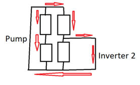
Think having the two MPPTS on at the same time creates a short preventing the pump inverter from seeing the full voltage on that string and potentially creating a situation where the other parallel strings could short through that path due to higher voltage than the center tapped string:

1708725677310.png
 
Back
Top