diy solar

diy solar

Center Tapping Solar Strings

Many charge controllers (most in fact) aren't fully isolated from the PV input to the battery side output- so you have one charge controller running at 0v (in relationship to the battery negative rail) and the other at 325v...

This is why I said before that the solar side HAS to be completely independent and separated, and the charge controller's connected only on the battery side...
(a hybrid inverter is just a 'charge controller and an inverter in the same box')
I have come across this far to often in the past when people share a common bus from multiple parallel arrays, and switch from one brand of charge controller to another- PWM could switch on either the negative or positive side and MPPT is usually (but not always) coupled on the negative side... So what works with one controller may not work with another...

The ONLY way to 'fix' this issue is with switching the array with appropriately rated DC relays ($$$) so it is either in series when the pumps VFD is running, or separated mid string when it isn't and the inverter is running/charging...
(or use a 1000V inverter/charge controller that can 'straddle' the whole string... again very few 'consumer level' inverters/charge controllers exist in this voltage range, as it is in the 'industrial' level equipment that you find them...
Be VERY cautious playing at these voltage and power levels- I seriously discourage non trained people from 'experimenting' with them- you can strike an arc that is VERY hard to extinguish and can jump quite long distances, and these voltages are LETHAL...

( I was trained with voltages and power levels in this range (a bit higher actually, 1600vDC at 20Ka on the electric trains lol) and am all too familiar with the dangers they present- you don't get a second chance with this stuff...)
 
Without examining it closely I suspect the parallel strings that are not center tapped, but still there, are causing a voltage differential issue. It was stated that, "The array has 6 strings of 14 panels in parallel to feed the drive."

With your 2 SCC trying to draw the voltage down on string 1 for loading the other 6 strings in parallel are seeing a place to discharge to.

This is just a quick surmise so don't shoot me if I missed something.
 
Many charge controllers (most in fact) aren't fully isolated from the PV input to the battery side output- so you have one charge controller running at 0v (in relationship to the battery negative rail) and the other at 325v...

This is why I said before that the solar side HAS to be completely independent and separated, and the charge controller's connected only on the battery side...
(a hybrid inverter is just a 'charge controller and an inverter in the same box')
I have come across this far to often in the past when people share a common bus from multiple parallel arrays, and switch from one brand of charge controller to another- PWM could switch on either the negative or positive side and MPPT is usually (but not always) coupled on the negative side... So what works with one controller may not work with another...

The ONLY way to 'fix' this issue is with switching the array with appropriately rated DC relays ($$$) so it is either in series when the pumps VFD is running, or separated mid string when it isn't and the inverter is running/charging...
(or use a 1000V inverter/charge controller that can 'straddle' the whole string... again very few 'consumer level' inverters/charge controllers exist in this voltage range, as it is in the 'industrial' level equipment that you find them...
Be VERY cautious playing at these voltage and power levels- I seriously discourage non trained people from 'experimenting' with them- you can strike an arc that is VERY hard to extinguish and can jump quite long distances, and these voltages are LETHAL...

( I was trained with voltages and power levels in this range (a bit higher actually, 1600vDC at 20Ka on the electric trains lol) and am all too familiar with the dangers they present- you don't get a second chance with this stuff...)
Thank you very much for the information and the advice it is very much appreciated

We are always looking to be safer in our installations, one for he reasons I’m trying to figure out what is going on with this site, is also to make sure we aren’t leaving something there that is potentially dangerous

Today we separated the solar arrays 56 to the inverters and 56 to the well drive (4 strings of 14)

2 questions for you

Could we isolate the charge controllers by installing diodes between the charge controller and the battery input effectively fully isolating them from the battery rail?

I think your idea has some merit and I’d be interested in ways to make this setup safe

Another question
Would separating the battery into 2 sides without a common bus, potentially fix the problem as you’ve described it?

That’s very easy as the bank is 60kWh and will be 100kWh by fall time
 
Yes I am thinking diodes might help to steer and isolate things from each other, as Bop said, inputs, outputs, batteries and MPPT's are not always isolated from each other.
They are going to be some serious diodes, be very careful.
 
Splitting the entire array isn't the issue (but may cause problems with the motor if there isn't enough power being fed to it...
Even a single 14 series panel string will have the same problem- it is (unless you physically split the series string in two) a 'shared solar side' connection...

1708743152482.png
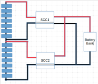
This is what you appear to be doing, going from your description...
The issue is that the PV string itself is not isolated from each half...they have a 'shared' connection in the middle of the string...
If you 'cut the string' at that point (ie between the red and black in the middle) so it becomes 'two totally separate 7 panel strings (and you would have to either do this at EVERY string in the array, or cut that string from the rest of the array at both ends) then effectively you have the charge controllers negative PVs at different levels...
As very few are totally isolated from PV input to Battery output (ie the grey links inside the two SCC's) You have a 'around' 325v difference across SSC1 from PV neg to bat neg connections, and the full array voltage (that 650v of the full array voltage) across the PV inputs on SCC1 to from the PV positive input to the the battery negative on it!!!
No wonder they are complaining (surprised either/both didn't let the magic smoke out!!!!)
the only way to fix this is have total positive isolation between the top 7 panels and the bottom 7 panels ie 'cut the wire' but that then leaves the motor VFD unable to operate...

To do both-you either need to dump the VFD altogether and run the motor directly from the inverter if possible, and dedicate the entire array permanently to the inverter- this means an inverter big enough to run the motor, plus any other loads you might add to it... and also means the inverter's internal SCCs need to be big enough to handle the array wattage or the array separated into smaller ones with multiple SCC's connected to each to handle the battery charging duties- or some pretty intricate (and high level) DC switching is going on, physically changing the arrays wiring connections depending on which load is connected to it (ie multiple high voltage, high current DC contactors triggered by the switching system on the pump itself...)
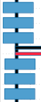
ie change this
1708744946083.png
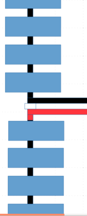
to this
1708744985976.png
Either permanently (with the motor on the inverter) or on every single string on the array with the VFD remaining in place by an appropriately rated contactor, and all of them switched as appropriate by the motor start circuit...
Not a job for the faint hearted...
 
Last edited:
Most inverters and SCC apply some bias or another on the PV strings. Either they ground it, or make it ride on the AC it is feeding (transformerless.)
If you fed a VFD with both AC and PV DC through additional diodes, that would also apply a bias.

If VFD was fed only DC, I think PV and motor leads would be free floating relative to ground. Anything driving or biasing it could potentially blow EMI filter capacitors and surge arrestors. Maybe this one is designed to withstand +/-800VDC and be OK.


An isolated DC/DC converter could work but wouldn't implement MPPT. Some electronic parts quote working isolation voltage of only a few hundred, even though they quote (brief) test voltage of a few thousand. Likely meant for powerline voltages and surges, not continuous elevated voltage.


These days, PV panels are the cheapest part, so independent systems is probably the way to go. Developing a product, switchable or isolated outputs could be a feature.
 
  • Like
Reactions: Bop
Back
Top