diy solar

diy solar

Do I need to "Ground" my small system in my van?

bobsacimano

New Member
Joined
Jun 30, 2023
Messages
14
Location
Thailand
I am trying to find out if I need to "ground" my solar system in my van. For reference, I have a 12v 100w panel screwed and sealed to the roof of my van, a 100ah Lifepo4 battery, 20mppt rover charge controller and a 700w pure sine inverter that has GFCI outlets. All from renogy. According to the manuals, it says the inverter should be grounded to the vehicle. Is this neccessary given the small size of my system and the existing GFCI's? Also is any other "grounding" required? Like the battery as I've heard from some people as well. There seems to be a lot of conflicting information on this subject especially for a rookie like myself. I put "ground" in quotations because I know everyone would jump all over me about it never being a true ground in a vehicle. I've heard that already. Any help would be appreciated. Thanks in advance!!
 
Yup.
Without it, any time you have anything powered from the inverter in your hand you will get a shock from the vehicle...
 
Read your inverter's documentation. A lot of the Chinese ones do not allow you to connect neutral to ground, ground is there as a ground for the equipment against static\lightning but you can't bond neutral to the battery negative without threat of a fire. Neutral floats on many inverters.

You can create an equipment ground but do not connect any leg of the AC output to ground unless it supports it. I think you can also use an isolation transformer as well in lieu of inverter support for it.

In my case, the battery has no connection to the trailer shell, because I know the inverter I am using has a floating neutral and it could start a fire if neutral touched the shell of the trailer if the battery's negative terminal was ground like a car.

If you can use a voltmeter and see voltage between bat neg and line on the inverter, it's probably not using an isolation transformer internally and true ground neutral bonding would result in smoke\fire\bad.

You don't want a "hot skin" scenario.
 
Last edited:
Yup.
Without it, any time you have anything powered from the inverter in your hand you will get a shock from the vehicle...
Thanks! Even if my outlets are GFCI outlets on the inverter? This shock would still happen? Also the Renogy manual says to ground the inverter to the vehicle chassis. With 14-18 AWG wire. I have 14 AWG wire I plan on using. Will this be thick enough? I know it's what the manual suggests but I have read other things saying you need a wire no more than 1 gauge less than the 1 on your inverter or battery or something. Plus it wouldn't be the first mistake I've noticed in Renogy's manual. Thanks in advance.
 
Last edited:
Read your inverter's documentation. A lot of the Chinese ones do not allow you to connect neutral to ground, ground is there as a ground for the equipment against static\lightning but you can't bond neutral to the battery negative without threat of a fire. Neutral floats on many inverters.

You can create an equipment ground but do not connect any leg of the AC output to ground unless it supports it. I think you can also use an isolation transformer as well in lieu of inverter support for it.

In my case, the battery has no connection to the trailer shell, because I know the inverter I am using has a floating neutral and it could start a fire if neutral touched the shell of the trailer if the battery's negative terminal was ground like a car.

If you can use a voltmeter and see voltage between bat neg and line on the inverter, it's probably not using an isolation transformer internally and true ground neutral bonding would result in smoke\fire\bad.
Thanks. It mostly went over my head but I think you were saying don't ground my solar battery to the vehicle? The Renogy (I don't know if that is 1 of the Chinese ones you are referring to) manual says to ground the inverter to the vehicle chassis. With 14-18 AWG wire. I have 14 AWG wire. The inverter also has a GFCI. So I just attach my 14 AWG wire to the inverter ground going to the vehicle chassis? Nothing more?
 
Size is irrelevant. Nobody wants to get shocked by stray voltage.

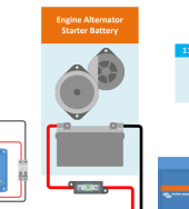
This Victron diagram shows the lynx bonded to chassis (battery negative) and the multiplus housing bonded to chassis (housing is internally bonded to AC ground):


Failure to properly ground and/or have a proper N-G bond is a common cause of GFCI outlet trips or improper function.
Thanks. I appreciate the input but that diagram is way above my current level of solar knowledge. It only confused me more. I believe it was a stationary system as well in the diagram but mine is mobile for what it's worth. It also appears to have several items that aren't in my setup so it just confuses the hell out of me. Thanks for trying to help though.
 
Thanks! Even if my outlets are GFCI outlets on the inverter? This shock would still happen? Also the Renogy manual says to ground the inverter to the vehicle chassis. With 14-18 AWG wire. I have 14 AWG wire I plan on using. Will this be thick enough? I know it's what the manual suggests but I have read other things saying you need a wire no more than 1 gauge less than the 1 on your inverter or battery or something. Plus it wouldn't be the first mistake I've noticed in Renogy's manual. Thanks in advance.
Yes.
The shock is from a difference in grounded potential. It isn’t like 120V or anything, it’s more like 30V or less, but it stings. Best to balance the potentials. And on the tiny inverter you are discussing, 14 awg is fine connected to the grounding lug on the side of the inverter. Not the same as the battery cables feeding the inverter.
700W isn’t a lot, so the wire size feeding the inverter to the battery needn’t be over #6 unless you are planning to install a larger inverter and wanna have the cable ready for it.
Ok thanks a lot man! I'm using 4 AWG cables from the battery to the inverter. So other than attaching the 14 AWG cable from the inverter ground lug to the vehicle chassis, do I need to attach anything else from my system to the vehicle chassis or do anything else to be properly "grounded" in a vehicle? Also someone mentioned on another forum that this shock you speak of when plugged into the inverter only happens if you're using a device with a metal case. Is that true? Usually the device will also have 3 prongs if it's encased in metal. This is just what I heard, not saying it's true. Just looking for clarification.Thanks in advance!
 
The goal is to keep all the exposed metal parts at the same potential. It's a mute point if you mount the inverter to the frame (metal to metal contact) but there is a chance of a poor electrical connection, hence the 14 AWG wire. This wire does not carry any current so size isn't too much of an issue. With your grounding wire, your inverter and van frame are the same potential (voltage) so you won't get shocked touching them. Your 3 wire cord extends the inverter ground to the metal of your device (drill, saw) so that the exposed metal case is at that same potential.
 
The goal is to keep all the exposed metal parts at the same potential. It's a mute point if you mount the inverter to the frame (metal to metal contact) but there is a chance of a poor electrical connection, hence the 14 AWG wire. This wire does not carry any current so size isn't too much of an issue. With your grounding wire, your inverter and van frame are the same potential (voltage) so you won't get shocked touching them. Your 3 wire cord extends the inverter ground to the metal of your device (drill, saw) so that the exposed metal case is at that same potential.
Thanks. I think I understood most of what you are saying. But to be clear, I should attach my 14 AWG wire to the ground lug on the inverter and the other end to the vehicle chassis? That will eliminate the risk of getting shocked when using metal cased objects that are plugged into my inverter?
 
Thanks. I think I understood most of what you are saying. But to be clear, I should attach my 14 AWG wire to the ground lug on the inverter and the other end to the vehicle chassis? That will eliminate the risk of getting shocked when using metal cased objects that are plugged into my inverter?
The 14 AWG will tie everything together to eliminate the shock hazard. The inverter GFCI is another line of defense.
 
The 14 AWG will tie everything together to eliminate the shock hazard. The inverter GFCI is another line of defense.
Thanks man! There's so much conflicting information out there regarding "grounding" in a vehicle. People have a tendency to write out long paragraphs using terms I don't know half the time and it's confusing and often incomprehensible to a rookie like myself. So I appreciate your simple explanation. I just hope you are right lol.
 
Thanks. I think I understood most of what you are saying. But to be clear, I should attach my 14 AWG wire to the ground lug on the inverter and the other end to the vehicle chassis? That will eliminate the risk of getting shocked when using metal cased objects that are plugged into my inverter?
Just to be clear...
The grounding lug is NOT the negative terminal for the inverter, but it is a dedicated grounding terminal or screw on the case of the inverter.
 
Thanks. I appreciate the input but that diagram is way above my current level of solar knowledge. It only confused me more. I believe it was a stationary system as well in the diagram but mine is mobile for what it's worth. It also appears to have several items that aren't in my setup so it just confuses the hell out of me. Thanks for trying to help though.

Stationary?

1688234443311.png
 
Just to be clear...
The grounding lug is NOT the negative terminal for the inverter, but it is a dedicated grounding terminal or screw on the case of the inverter.
Yes I know that. It's a tiny spot on the DC side on my inverter that says ground. Thanks for the heads up though.
 
I guess I missed that pic lol. I seen the picture of the antenna and it said "grid" so I figured it was a stationary system. But nonetheless it's still very confusing to me. It has multiple batteries, multiple charge controllers, multiple solar panels, transformers, shunts, etc. Again I appreciate you trying to help me but that diagram isn't helping me at all unfortunately. My setup is much simpler than the 1 in the diagram. 1 battery, 1 panel, 1 charge controller, fuses between my positives, battery monitor and inverter. Thanks for trying to help though.
 
I guess I missed that pic lol. I seen the picture of the antenna and it said "grid" so I figured it was a stationary system. But nonetheless it's still very confusing to me. It has multiple batteries, multiple charge controllers, multiple solar panels, etc. Again I appreciate you trying to help me but that diagram isn't helping me at all unfortunately. Thanks though.

Title of the diagram:

Lucians Victron Van - Automotive

It's not very complicated, and I pointed out the important parts - where the grounds were: The lynx, which is battery (-) and the Multiplus housing grounding terminal.

I really recommend you put in 15 minutes tracing connections. It's a trivial matter to ignore the parts that don't apply to you.
 
Back
Top