Plenty of information on these forums to get you started learning the new stuff!


You are using an out of date browser. It may not display this or other websites correctly.
You should upgrade or use an alternative browser.
You should upgrade or use an alternative browser.
RV Question about solar panels, controllers, and batteries
- Thread starter datdude
- Start date
datdude
New Member
It would be great if someone knows a place they can point me to to learn something. I know I need to put in work and I am and will, but instead of just saying "you're using the wrong words good luck," just point me somewhere and will go learn it best I can.
Thanks to the internet there is many places you can find information. For instance if you Google "Fundamentals of heat transfer" there are many resources including videos and books. Or you can search "understanding Solar Energy".
RV8R
Solar Enthusiast
So I have asked this in an RV forum and did not get the response I was hoping for. So I thought I would post it here.
I keep hearing that you need to disconnect your panels from your controller if you are going to remove your batteries. I understand that if you do not you will have live wires in the battery bay after you remove them. But I keep seeing the myth that your solar controller will burn up if you do that because it will convert the energy from the solar panels into heat and cook itself. So if you can help me understand something, I would greatly appreciate it.
Myth or Fact: If you do not disable or disconnect the solar panels from the solar controller, you risk burning up your controller if a battery is not also connected to the controller.
I can see the logic in the myth and don't necessarily doubt that this could happen with some controllers.
But, what is the difference in the scenario where your batteries are disconnected and unable to absorb the engery and the batteries being 100% SOC and unable to absorb the energy?
If the controller somehow manages the panel side of the circuit and opens it somehow when the batteries are full, why doesn't it fail the panel circuit open when batteries are not present to protect itself? Or does this already happen in some fashion and the myth remains a myth?
I am hopeful someone can explain the how and why here. I can and will test it sometime myself but am hopeful someone else has done this or has specific knowledge.
My intention when I have the trailer out next is to measure voltage on the controller to negative battery terminal while it is disconnected in the sun and see if voltage is flowing into the batteries when the controller is powered off since I think it is powered from the batteries and not the solar (is this generally true?). That should tell me whether the controller is disconnecting the panels when powered off. I will also pull the controller out and try to measure heat on the unit / heatsink.
For particulars about my setup:
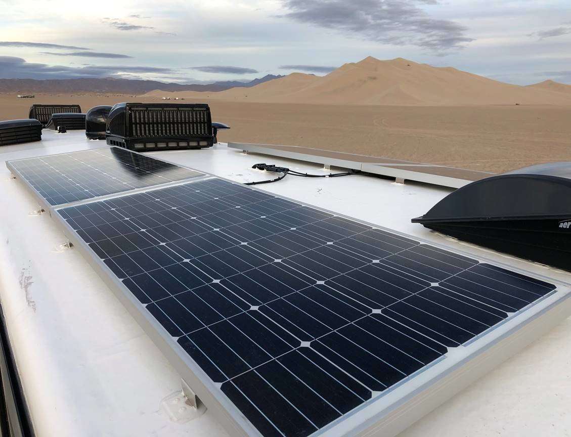
Factory installed Go Power 570w kit with non-bluetooth PWM 30 amp controller and 3x190w panels and 1500w inverter with transfer switch. Everything there is factory and connected to 2x100ah GoPower LFP batteries which are also non-bluetooth. I do have a Victron smartshunt with bluetooth.
If anyone has any input to any of this, or has already done this type of thing, please please let me know.
Thanks all
I came across the following thread, & thought it might shed some light on the topic for you @datdude

Why do we use a PV disconnect that breaks both the positive and negative side of a PV circuit?
Why do we use a PV disconnect that breaks both the positive and negative of a PV circuit? The flippant answer is that the NEC requires it...... but that does not really explain why. What the NEC actually requires is the disconnect breaks all conductors that are not solidly grounded. Since...
 diysolarforum.com
From your original post I am attempting to extract your questions ,,, I assume they are;
1) Disconnection Procedures of Solar Systems / Myths & Facts / burning up equipment / proper procedures
2) Battery disconnected vs 100% SOC difference
3) Is the controller powered from the batteries when the controller is “off” ?
4) Does the controller disconnect the panels when “powered off” ?
My thoughts;
1) I think “it depends”. I believe older controllers had procedural issues of disconnecting out of sequence, but I have no experience with older equipment. For “safety” reasons, procedures are typically in place. The above thread I posted for you is a good read into NEC & the questions of why & disconnects, etc, etc. Also your question can nit be answered for all equipment for all system designs. If you want to know about this on your specific RV for ne to “parse” thru it I would need the schematics & equipment info from the manufacturers ,,, manuals ,,, performance specifications, etc. Can you “burn up” your equipment if you do something wrong ,,, yep ,,, depends what you do wrong ,,, sometimes it is fire & sometimes it is magic smoke ,,, sometimes it is just “dark”. On my system, I “disconnect” my array ( 1st thru the Victron app “stop feeding the load” & then manually disconnecting the PV + & - wires ) then disconnect the battery. I also disconnect the negative battery terminal first on NA vehicles ,,, but hey that is just me.
2) a battery connected to a controller ( in my case ), powers the controller & suggests it is a 12vdc battery bank rather than a 24vdc bank. The controller is “on” if the battery is connected. Without the battery being “on” first I can’t access the Bluetooth to view the system. When the battery is connected my understanding is the controller reads the resistance ( of the battery & system ) & controls the charge or energy flow accordingly. Where as a disconnected battery / system would “open that circuit” & the controller stops. I am not an electronics expert at all, but I assume the energy from the array at that point is not being dissipated thru the controllers heat sink.
3) I am not sure I have this question right ,,, but the controller is powered by the batteries when the array is disconnected. When the array is connected & the controller is receiving energy from the array ( daytime ) the controller is giving energy to the batteries. When the sun goes down / or the array is “disconnected” the controller gets the energy from the batteries.
4) No ( in the NEC description of “Disconnect”) ,,, again refer to the link above. Disconnecting the array is a physical opening up of the arrays + & - circuit. My Victron can “turn off” the charger ( an App switch that stops feeding the “load”) & I do turn off the load before “disconnecting” my array wires. MC4 connectors should never be disconnected “under load”. There is a major difference between AC & DC, the following video will show you this @ about 1:08 timeframe into the video when he switches from AC to DC
 ;
;This is about the best visual reference I have found to understand MC4 connectors which are used in solar panels which is DC.
Does the controller, control the energy from the solar array wires - yes thru electronics it can stop feeding the load ( or at least my Victron can ).
Last edited:

datdude
New Member
Thanks for the info RV8R. Just in case it was not clear, my particular use case is a very small (3 panelx190w ea) RV system that was provided OEM. GoPower branded, PWM controller, 2x100ah LFP.
ETA: I also have a Victron SmartShunt that I forgot to mention. 1500w GoPower inverter, 65am WFCO 9865-AD converter. That is about it I think.
ETA: I also have a Victron SmartShunt that I forgot to mention. 1500w GoPower inverter, 65am WFCO 9865-AD converter. That is about it I think.
Last edited:
RV8R
Solar Enthusiast
Thanks for the info RV8R. Just in case it was not clear, my particular use case is a very small (3 panelx190w ea) RV system that was provided OEM. GoPower branded, PWM controller, 2x100ah LFP.
ETA: I also have a Victron SmartShunt that I forgot to mention. 1500w GoPower inverter, 65am WFCO 9865-AD converter. That is about it I think.
If you are able to draw a schematic of what you intend to ( or already ) have in place that can also be helpful.
You could get that schematic “fleshed out” here by other members that might be more experienced with that gear. Manuals should be available online.
“Go Power” ,,, I stumbled into their office one day ,,, A spin off of Carmanah batteries IIRC
Contact Go Power!
Need a hand? Contact us with your support questions for mobile solar power for trailers, RVs, fleet trucks, and marine applications.
 gopowersolar.com

Anyway, they originated in my home town.
so is Carmanah Technologies;

Last edited:
datdude
New Member
I really don't have any issues with my setup right now. Everything is working great with only one exception.
When I have drained my batteries such that I need a full bulk mode cycle (my converter will run up to 4 hours in bulk (14.4v) before falling back to absorption (13.6v) - these are the words they are using. All good so far.
What happens during the day is that the solar interferes with the converter such that the converter exits bulk mode after an hour because it is not detecting sufficient net load and goes into absorption mode prematurely. I have not had time to play with how much of a load I can put on the 12v to offset the solar charging, but I don't think I can get there reasonably, nor do I really want to.
1. If I am going to be on shore power, I don't care and would just live with this as it will be charged by the next day, it will just take longer to get there (yes, 13.6v will charge my LFP to 100% SOC).
2. If I am looking at needing to run my Onan LP 5500 (sorry I did not include that???), I do not want the charge to be in absorption mode any sooner that nit needs to be.= for obvious reasons.
3. If I install a disconnect switch on the OEM solar, I can prevent it from interfering with the detect functions on the converter and it will stay in bulk mode for up to 4 hours before dropping to absorption. 4 hours is the time limit for bulk. If they were really low, I could just power cycle the converter to start charging in bulk mode again.
4. So part of my initial question was going to be whether I should install a disconnect between the PV and SCC, or whether it was sufficient to just install one at the batteries (this will be much easier). But I heard horror stories (myths?) that leaving PV connected to SCC without load could fry SCC, which I didn't want. It seems that is not a problem and my SCC has no autodetect function - so I don't think there is really much (any?) risk either way. And here we are lol.
5. In my last test with the trailer in the storage building I was able to prove out #3 since there was no solar coming in.
This is quite a rabbit hole to go down and I feel like I am learning a lot for such a short time and am reading posts and the stuff others have provided as quickly as I can.
For the schematic, I can put something together but it might take me a bit to get that done. I have to find somewhere to build one (draw.io maybe?).
RV8R
Solar Enthusiast
I really don't have any issues with my setup right now. Everything is working great with only one exception.
When I have drained my batteries such that I need a full bulk mode cycle (my converter will run up to 4 hours in bulk (14.4v) before falling back to absorption (13.6v) - these are the words they are using. All good so far.
What happens during the day is that the solar interferes with the converter such that the converter exits bulk mode after an hour because it is not detecting sufficient net load and goes into absorption mode prematurely. I have not had time to play with how much of a load I can put on the 12v to offset the solar charging, but I don't think I can get there reasonably, nor do I really want to.
1. If I am going to be on shore power, I don't care and would just live with this as it will be charged by the next day, it will just take longer to get there (yes, 13.6v will charge my LFP to 100% SOC).
2. If I am looking at needing to run my Onan LP 5500 (sorry I did not include that???), I do not want the charge to be in absorption mode any sooner that nit needs to be.= for obvious reasons.
3. If I install a disconnect switch on the OEM solar, I can prevent it from interfering with the detect functions on the converter and it will stay in bulk mode for up to 4 hours before dropping to absorption. 4 hours is the time limit for bulk. If they were really low, I could just power cycle the converter to start charging in bulk mode again.
4. So part of my initial question was going to be whether I should install a disconnect between the PV and SCC, or whether it was sufficient to just install one at the batteries (this will be much easier). But I heard horror stories (myths?) that leaving PV connected to SCC without load could fry SCC, which I didn't want. It seems that is not a problem and my SCC has no autodetect function - so I don't think there is really much (any?) risk either way. And here we are lol.
5. In my last test with the trailer in the storage building I was able to prove out #3 since there was no solar coming in.
This is quite a rabbit hole to go down and I feel like I am learning a lot for such a short time and am reading posts and the stuff others have provided as quickly as I can.
For the schematic, I can put something together but it might take me a bit to get that done. I have to find somewhere to build one (draw.io maybe?).
Schematic ,,, “Pen & Paper & Photo & Post” ,,, not looking for “Professional Quality here - just a chicken scratch to begin with.
FYI, this is the first post of yours on here where I actually understand your problem & why you are asking questions & that you have an Onan
 ,,, I feel we are getting somewhere now.
Basically you have parallel chargers operating simultaneously that are not necessarily “playing well with each other” ,,, got it ,,, lets get that sorted out for you

Regarding your solar charger - what does the manual or manufacturer say about disconnecting procedures ??
I typically do not have multiple chargers running simultaneously on my 12vdc systems as I simply don’t need them. But I believe “The Forum” can help sort out your multiple charger issue.
FYI ,,, IIRC “Renogy” has a dual ( alternator / solar ) 50amp & a poor logic IMO of only allowing 25amps each when both are available ,,, & that is in 1 magic box
. What that boils down to is only 25amps from the alternator when on crappy solar days & driving.So I understand you wanting to know how these things work & how to get them to play nice together.
If you get the info from your Solar Charger, you will discover the “right way” to stop that charger. If it is by opening the PV wire circuit get a decent “disconnect”;
PV Disconnect for 600W Array ( 60 V @ 10 A )
For my remote cabin, I am considering a “Combiner Box” or a “Breaker” for the “Primary” function as a PV Array “Disconnect”. Currently I have 6 100W panels 3S2P so roughly 600W ( 60 volts @ 10 amps ). I have a Victron 100 | 50 MPPT I consider the combiner box a choice for future upgrades, but...
diysolarforum.com

mppt fuse question
@datdude ,,, I am bulk posting here for you to attempt a lot of info as I think you are thirsty for it. The following is important IMO in the “Internet DIYer World” ,,, kinda goes hand in hand with “Trust but Verify” ,,, Anyway in the DIYer Van Design / Build it is like the Wild West of “Blind leading Blind” with surface scratched just learned info & “Parroting” without a very deep knowledge base ,,, Just do this - I did
;
So “Even” with a properly rated “Disconnect” ,,, IMO, it would be “Best Practice” to always use that disconnect after turning the “load” off ,,, thus only using the ability of the “disconnect” under load in an emergency situation. I suppose some could fault me with that perspective ,,, but I would need to know why.
Last edited:
RV8R
Solar Enthusiast
This ;

Yup ,,, Like taking a drink from a Fire Hose;
None of us were born knowing any of this, so just a process of learning & sharing experiences with others.
There are 3 things in this World;
1) Things we know
2) Things we know we don’t know
3) Things we don’t know we don’t know
Outta all of these things #3 will bite you in the Butt, the most.
;Yup ,,, Like taking a drink from a Fire Hose;
None of us were born knowing any of this, so just a process of learning & sharing experiences with others.
There are 3 things in this World;
1) Things we know
2) Things we know we don’t know
3) Things we don’t know we don’t know
Outta all of these things #3 will bite you in the Butt, the most
.datdude
New Member
The manual for my SCC is lacking as is for the rest of theGoPower equipment (the inverter is not AS bad as the others). This kit is really intended for the lowest common denominator. I am posting the product links for those who are curious what I mean here. Each has a documents section on them.Schematic ,,, “Pen & Paper & Photo & Post” ,,, not looking for “Professional Quality here - just a chicken scratch to begin with.
FYI, this is the first post of yours on here where I actually understand your problem & why you are asking questions & that you have an Onan
Basically you have parallel chargers operating simultaneously that are not necessarily “playing well with each other” ,,, got it ,,, lets get that sorted out for you
Regarding your solar charger - what does the manual or manufacturer say about disconnecting procedures ??
I typically do not have multiple chargers running simultaneously on my 12vdc systems as I simply don’t need them. But I believe “The Forum” can help sort out your multiple charger issue.
FYI ,,, IIRC “Renogy” has a dual ( alternator / solar ) 50amp & a poor logic IMO of only allowing 25amps each when both are available ,,, & that is in 1 magic box
So I understand you wanting to know how these things work & how to get them to play nice together.
If you get the info from your Solar Charger, you will discover the “right way” to stop that charger. If it is by opening the PV wire circuit get a decent “disconnect”;
PV Disconnect for 600W Array ( 60 V @ 10 A )
For my remote cabin, I am considering a “Combiner Box” or a “Breaker” for the “Primary” function as a PV Array “Disconnect”. Currently I have 6 100W panels 3S2P so roughly 600W ( 60 volts @ 10 amps ). I have a Victron 100 | 50 MPPT I consider the combiner box a choice for future upgrades, but...
mppt fuse question
www.promasterforum.com
@datdude ,,, I am bulk posting here for you to attempt a lot of info as I think you are thirsty for it. The following is important IMO in the “Internet DIYer World” ,,, kinda goes hand in hand with “Trust but Verify” ,,, Anyway in the DIYer Van Design / Build it is like the Wild West of “Blind leading Blind” with surface scratched just learned info & “Parroting” without a very deep knowledge base ,,, Just do this - I did
So “Even” with a properly rated “Disconnect” ,,, IMO, it would be “Best Practice” to always use that disconnect after turning the “load” off ,,, thus only using the ability of the “disconnect” under load in an emergency situation. I suppose some could fault me with that perspective ,,, but I would need to know why.
Battery:
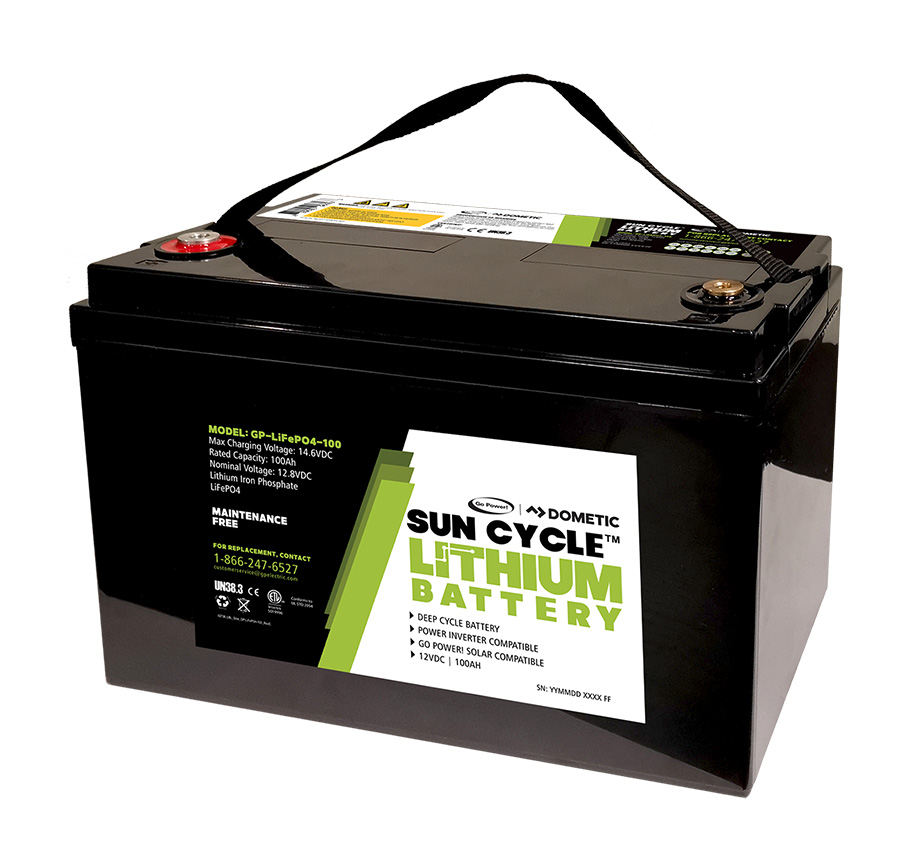
100Ah Lithium Iron Phosphate Solar Battery
Go further off-the-grid with the new Go Power! 100ah Lithium Iron Phosphate Solar Battery designed specifically for solar and inverter use.
gopowersolar.com
SCC:
Inverter + TS:
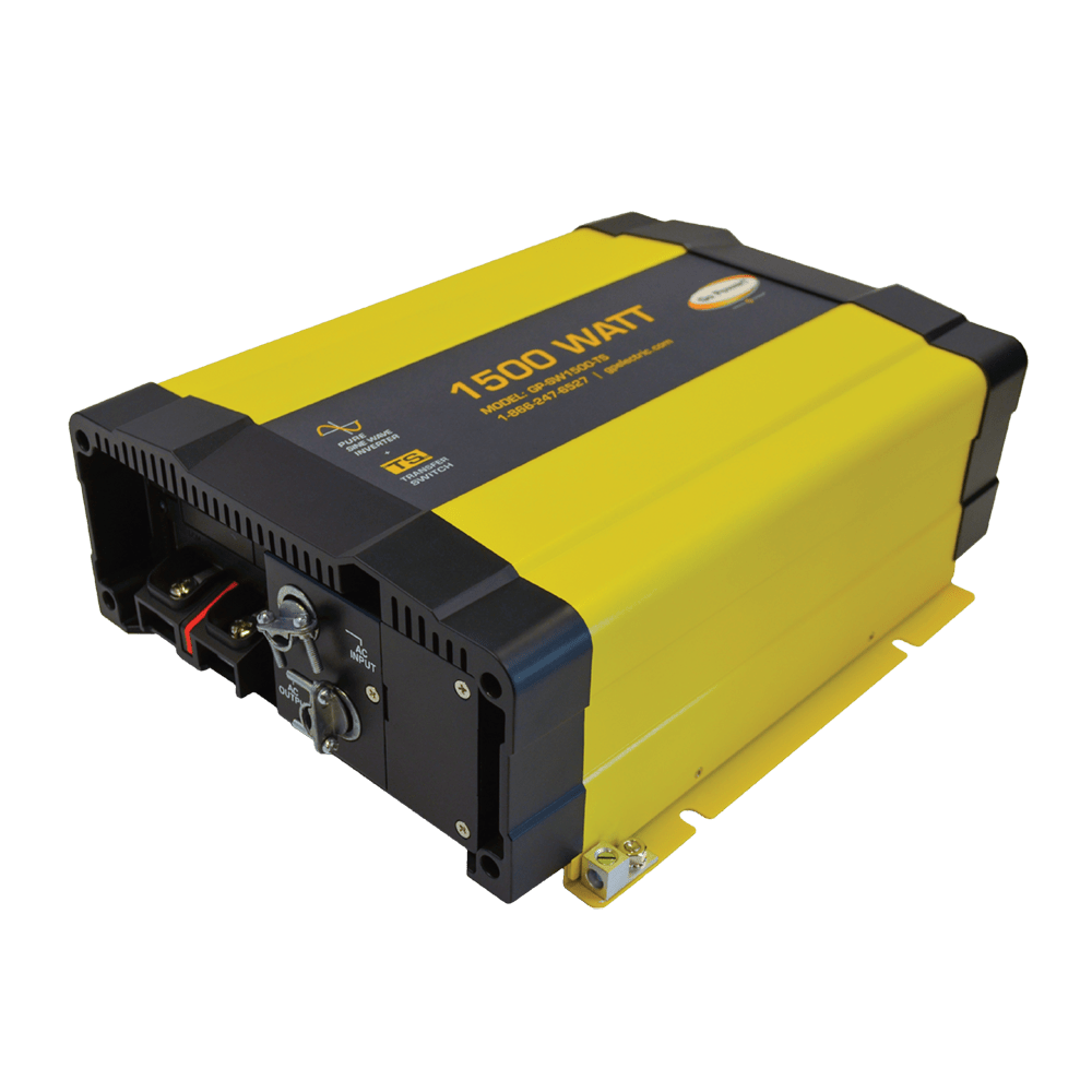
1500-watt Pure Sine Inverter & Transfer Switch
Go Power!’s GP-SW1500-TS pure sine wave inverter with transfer switch provides robust cUL certified AC power.
gopowersolar.com
Converter - WFCO 9865AD:
ETA:
PV (they were 190w when I got then, now say 200w, and this doesn't match exactly the "kit" I got):
My converter is in LFP mode. Some folks have difficulty getting the AD to work, but it is working for me.
datdude
New Member
Sorry - fixed the 7-pin route. Sorry this is so rough.

datdude
New Member
This exceprt fromt he converter manual covers what I see I think:
BULK MODE
This mode is designed with 2 purposes in mind. First, to quickly restore the energy back into
the battery. Second, to ensure the lithium cells inside the battery remain balanced. This is
accomplished by boosting the output voltage to 14.6 VDC and allowing the maximum current
to flow as required by the loads.
The bulk mode stage could last anywhere from 1 to 4 hours based on the battery and load
current which is being used. For a full battery, the bulk stage has a minimum time requirement
of 1 hour, which allows the lithium cells inside the battery the time required to “balance”. For an
empty battery, the bulk stage has a maximum time requirement of 4 hours. If your application
requires longer than 4 hours (such as a larger battery bank > 200 Ahr), a simple cycling of power
will reset the timers.
As the energy is restored into the battery, the DC system voltage will climb and the current from
the converter will decrease. If the total amperage draw from the converter reaches a preset point
(within the 1-to-4 hour timer), the converter is designed to drop out of bulk mode.
Boomerweps
New Member
I don’t understand the video. He intentionally shorted the breakers.
Was it to prove the DC arc would overpower the circuit breaker?
Or/and the CB is not able to properly open under overload conditions and provide needed protection?
I recently added a similar CB to route my RV’s 400 watts of panels through to my SCC.
Was it to prove the DC arc would overpower the circuit breaker?
Or/and the CB is not able to properly open under overload conditions and provide needed protection?
I recently added a similar CB to route my RV’s 400 watts of panels through to my SCC.
RV8R
Solar Enthusiast
I don’t understand the video. He intentionally shorted the breakers.
Was it to prove the DC arc would overpower the circuit breaker?
Or/and the CB is not able to properly open under overload conditions and provide needed protection?
I recently added a similar CB to route my RV’s 400 watts of panels through to my SCC.
I do not remember the voltage, but it is to show that the DC arc created would overpower the breaker’s ability.
Here is a video on 220V ,,, AC vs DC to demonstrate the difference ( very visual );
With the above in mind, depending on the voltage one can visualize the gap needed it break the arc.
For the various electrical systems members build on this forum, the maximum voltages that any system can produce might be considered when designing DIY systems.
In another hobby of mine, we use diodes to protect against “a collapsed magnetic field” ,,, you know a solenoid
,,, here is another video for ya to ponder ( a system voltage x 100 ) ;
Last edited:
Similar threads
- Replies
- 8
- Views
- 431
- Replies
- 13
- Views
- 492
- Replies
- 41
- Views
- 1K