diy solar

diy solar

RV Solar, charging and battery upgrade plan

ThrottleAbuse

New Member
Joined
Aug 18, 2022
Messages
22
Hello, I am currently in the process of planning and upgrading my RV power system.

I am replacing my 4 worthless 6v 230Ah batteries with 2 Epoch 300Ah V2 lithiums. To do so I need to add a DC to DC charger and I want to be able to charge the lithiums as quickly as possible when driving my RV or running my generator.

I also plan on adding some additional solar which I would like some help picking the specs and components. I have purchased a Renogy IP67 50 DC to DC MPPT charger. I will be using the 50A Renogy as the controller for it so that unit will handle DC to DC and the added solar. Right now I was thinking three 200W 24V panels and one 100W 24V panel all wired parallel. I had seen some on Richsolar that would work but now I cant find the 100W 24V panels. I dont have any preference here I just want to maximize the controllers capacity. The controller is rated for 720W so this should max out the controller. I have lost of room on the roof. 6 or 7 panels will easily fit. Renogy recommends a 60A and 70A fuse on the output and input sides.

I also plan on adding a Recpro 125A AC to DC charger to boost charging capacity while on shore power or while running the generator. I will wire this to an open breaker on the current 120V system that only runs on shore or generator power. I am not particularly attached to the Recpro but this seems like a pretty basic use case so it doesnt seem like I need something expensive. I believe I will be able to mount it close enough to run 4awg wire. I may need to increase that to 2awg. Is a ANL 175A fuse safe here?

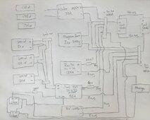
Here is a drawing of what I have planned. The Jaboni solar system is already installed and I am not 100% sure on how its connected but by knowing the specs I think all three 175W panels are wired in parallel. I also already have a Magnum 3000W inverter thats already installed. I will be disabling the auto merge and leaving a manual option to join house and chassis batteries.

For the battery install I see people recommending MBRF fuses. Do I just need a 600Ah fuse on the bus bar side since each batteries BMS is rated for 300A max draw? Do I need any other fuses on the battery part of this upgrade? 4/0 awg wire should be ok here between batteries and to the bus bars. Distances will be short.

Any advice on any part of this upgrade is much appreciated.
 

Attachments

  • 20240404_135029.jpg
    20240404_135029.jpg
    158.1 KB · Views: 19
Last edited:
You need larger wiring like everywhere. Your fuses are to protect the wiring and need to be below the wire ampacity. limit
 
You need larger wiring like everywhere. Your fuses are to protect the wiring and need to be below the wire ampacity. limit

Thank you for the reply. I used a calculator for the wire sizes. Did I not use it correctly? For the 125A charger for example if the 1 way run is less than 5ft it calls for 4 awg wire. Should I be basing it off the fuse size?

Just edited to add I realized I wrote 8 awg wire for the connection to the RV's current 12v system. I wont be replacing that and I dont know what is currently in there but I am assuming its sufficient.
 
Make sure to check your desired battery data sheet for the official charge and discharge rates.

From this, it is good to reduce this some to reduce the chance of overheating or shut down on hot days. For example try to use it in the 50 - 70% of these numbers or less.

Batteries are not an infinite supply or charge rate. That is one of the difference between more expensive and less expensive batteries.

Sometimes (often ) this requires using more, smaller batteries vs fewer larger batteries in a design.

_______________

Just as an example, suppose that a specific battery data sheet recommends a "continuous max charge rate" of 100 amps.

( 100 amps ) x ( 60% ) ~ 60 amps charge rate goal per battery.

For 2 each batteries, this is ( 2 batteries ) x ( 60 amps ) ~ 120 amps charging rate goal.

____________________

Now add up ALL of the charging sources for a total current that could be put in if all of them are operating and make sure that it is below this 120 amps charge rate goal.

If not, then "something" needs to change.

The "change" might be your electrical system, but it also could be just awareness of how you use the electrical system.
 
Some good thoughts HarryN. The Epoch batteries have a recommended charge rate 80A each. So maybe I should shelve the additional 125A charger and see how the setup goes with the added solar and new batteries. I was going to do the charger first and additional solar second but I think I will swap that order. With my lead acid setup I had little capacity I was running the generator much more than I wanted. Fuel is cheaper than all of this but I just rather not listen to a generator if I dont have to.
 
Thank you for the reply. I used a calculator for the wire sizes. Did I not use it correctly? For the 125A charger for example if the 1 way run is less than 5ft it calls for 4 awg wire. Should I be basing it off the fuse size?

Just edited to add I realized I wrote 8 awg wire for the connection to the RV's current 12v system. I wont be replacing that and I dont know what is currently in there but I am assuming its sufficient.
What calculator did you use? I use this and then if long runs go a gauge higer.

125a should be 2gauge at least. Basically everything needs to be 1 size larger.

I'm not sure the charge rate of the Magnum but if its like 100a then it'll take 6 hours to charge from 0. This might sound like a long time but it shouldn't matter much unless you're exclusively boondocking and running genset to charge.
 
What is currently installed and operating?
What is purchased but not installed?
 
Some good thoughts HarryN. The Epoch batteries have a recommended charge rate 80A each. So maybe I should shelve the additional 125A charger and see how the setup goes with the added solar and new batteries. I was going to do the charger first and additional solar second but I think I will swap that order. With my lead acid setup I had little capacity I was running the generator much more than I wanted. Fuel is cheaper than all of this but I just rather not listen to a generator if I dont have to.

Hi @ThrottleAbuse

What @HarryN & @corn18 wrote are important.

I might of missed it, but on the alternator side, I did not see what juice you can expect ?

I prefer the Kisae 1250 or now the 12100 as the max amps can be “user controlled / programmed”.


I am just starting to look at your schematic, but note the amperage difference for the inverter vs the rest of the equipment. I might consider splitting the wiring paths from the battery bank into ( 1 Inverter ) & ( 2 Everything Else );

IMG_1364.jpeg

With that inverter “out of the way” you might be able to utilize something like a “Safety Hub 150” for both pos / neg bus & fuse block 🤷‍♂️;

IMG_1355.jpeg


IMG_1354.jpeg


Are you intending on using 600 amps out of your Epoch Bank? I’m all for planning for future additions / use, but if you look at what your needs are now & what they might become “load calculations” I think it best to be realistic for “now” & “future”.


You didn’t list the RV Loads, but other than the inverter your amps are;

30
125 ( which I understand you are pondering a reduction here ? ) AC2DC charger
50
?? RV Loads


What amps do you expect to be pulling out with the inverter ?
 
Last edited:
What calculator did you use? I use this and then if long runs go a gauge higer.

125a should be 2gauge at least. Basically everything needs to be 1 size larger.

I'm not sure the charge rate of the Magnum but if its like 100a then it'll take 6 hours to charge from 0. This might sound like a long time but it shouldn't matter much unless you're exclusively boondocking and running genset to charge.
I was using this one


There are a few others and they had the same results.


I didnt actually crunch the calculations since I was getting similar results a few places.
 
What is currently installed and operating?
What is purchased but not installed?
Currently the Smaller Jaboni controller and solar system and the magnum inverter are all installed from the factor. My RV is a Tiffin Allegro Red 33AA. Its a 35' diesel pusher that has a 8000W generator.

I already purchased the Renogy IP67 DC to DC MPPT and the two Epoch 300Ah batteries. I have a fairly good handle on power needs. So I am working on installing these two first and foremost. The second solar system and the AC to DC charger are also in the works.
Coolio. So you must have a converter/charger somewhere in the coach already. I don't see one in your diagram. Also, is your AC system 50A or 30A?
 
I was using this one


There are a few others and they had the same results.


I didnt actually crunch the calculations since I was getting similar results a few places.
1712328882893.png
Something's up with that calculator. According to it I can run 1000a on 2gauge wire for 1foot and it wouldn't even get to 70F

These are more voltage drop calculators and in short distances we're more concerned about melting wires and causing fires.
 
Currently the Smaller Jaboni controller and solar system and the magnum inverter are all installed from the factor. My RV is a Tiffin Allegro Red 33AA. Its a 35' diesel pusher that has a 8000W generator.

I already purchased the Renogy IP67 DC to DC MPPT and the two Epoch 300Ah batteries. I have a fairly good handle on power needs. So I am working on installing these two first and foremost. The second solar system and the AC to DC charger are also in the works.

That’s a big rig ,,, & depending upon the year etc & has integrated “modules”.
Have family that works for Spyder “Canada”.


With my initial post to you, if I knew it was a Tiffin, that would have changed the way I thought about it.
 
Hi @ThrottleAbuse

What @HarryN & @corn18 wrote are important.

I might of missed it, but on the alternator side, I did not see what juice you can expect ?

I prefer the Kisae 1250 or now the 12100 as the max amps can be “user controlled / programmed”.


I am just starting to look at your schematic, but note the amperage difference for the inverter vs the rest of the equipment. I might consider splitting the wiring paths from the battery bank into ( 1 Inverter ) & ( 2 Everything Else );

View attachment 207246

With that inverter “out of the way” you might be able to utilize something like a “Safety Hub 150” for both pos / neg bus & fuse block 🤷‍♂️;

View attachment 207247


View attachment 207248


Are you intending on using 600 amps out of your Epoch Bank? I’m all for planning for future additions / use, but if you look at what your needs are now & what they might become “load calculations” I think it best to be realistic for “now” & “future”.


You didn’t list the RV Loads, but other than the inverter your amps are;

30
125 ( which I understand you are pondering a reduction here ? ) AC2DC charger
50
?? RV Loads


What amps do you expect to be pulling out with the inverter ?

Alternator is a 160A unit on a ISB 6.7 Cummins. So the Renogy 50A should be safe for the alternator.

The Magnum invertor is already installed so I was just using the bus bar to simplify the install of the new batteries. My thought process was on bus bar pair for all the 12v connections to the batteries. When you say split do you mean just bypass the bus bar and go straight to the battery bank for the Invertor? I think the bus bars are over specced because it will likely only be 325A max. Max charge rate of the invertor is 125A. According to the spec sheet it has a max draw of 400ADC.

I guess I dont know what the max draw would be from the Epochs. I am not adding or changing any of the draw requirements for the RV. I dont know the best way to calculate the draw requirments since there are so many items in the system already. Just would like to make it theough the night without the genny firing up or having nearly dead house batteries in the morning.
 
That’s a big rig ,,, & depending upon the year etc & has integrated “modules”.
Have family that works for Spyder “Canada”.


With my initial post to you, if I knew it was a Tiffin, that would have changed the way I thought about it.
I should have put it in my original post now that I think about it. It a 2021. I have spoke to the spyder folks on how to disable the auto merge. Also since many of the systems are already installed I assumed it would be an easier project to tackle. My main concerns are just getting the new batteries installed safely and the Renogy unit installed safely to keep alternator charging working. I also want to spec out the second solar system because it would be nice to have more juice there. I asked to have a 6 panel system from the factory but they said it wouldnt fit. I think my salesman was just being lazy or it was during covid and tiffin didnt want to add the second 3 panel system like the more expensive coaches have.
 
The Blue Sea Systems calculator is the only one I ever use.


Thanks for the link. That calculator is giving me the same results as the other but I like the interface. So for the 125A DC to DC charger I put in my info as follows 12v, 125A, 10 ft round trip length. For CCA I put max draw allowed by bms of 600A and selected branch since its not the main lead off the battery. Are these the correct inputs? Suggests a 141A fuse so I should bump that to 150A correct?
 

Attachments

  • Screenshot_20240405_093813_Chrome.jpg
    Screenshot_20240405_093813_Chrome.jpg
    91 KB · Views: 2
Thanks for the link. That calculator is giving me the same results as the other but I like the interface. So for the 125A DC to DC charger I put in my info as follows 12v, 125A, 10 ft round trip length. For CCA I put max draw allowed by bms of 600A and selected branch since its not the main lead off the battery. Are these the correct inputs? Suggests a 141A fuse so I should bump that to 150A correct?
You need to set the wire insulation temp rating to match what wire you're using 60c is pretty normal.

The fuse should be below the wire rating which is 160a, I think you'd be fine with 150a in that scenario but I'm betting its at 105C which means the wire inside the insulation is above boiling water.
 
My gut tells me to take this slow. Just install the LiFePO4 and see how that does for you. You don't need to change anything to plop LiFePO4 into an FLA system. It won't be optimized, but it won't make blue smoke, either. Once you have some data, then start looking at optimizing it.
 
You need to set the wire insulation temp rating to match what wire you're using 60c is pretty normal.

The fuse should be below the wire rating which is 160a, I think you'd be fine with 150a in that scenario but I'm betting its at 105C which means the wire inside the insulation is above boiling water.
The wire I was planning on using is from Amazon seller recommeded by Will in his solar builds. Windynation. Shows its 105 rated.

2/0 Gauge 2/0 AWG 5 Feet Red + 5 Feet Black Welding Battery Pure Copper Flexible Cable + 10pcs of 3/8" Tinned Copper Cable Lug Terminal Connectors + 3 Feet Black Heat Shrink Tubing https://a.co/d/btTPjNm
 
Back
Top