justinm001
Solar Addict
- Joined
- Dec 18, 2022
- Messages
- 1,569
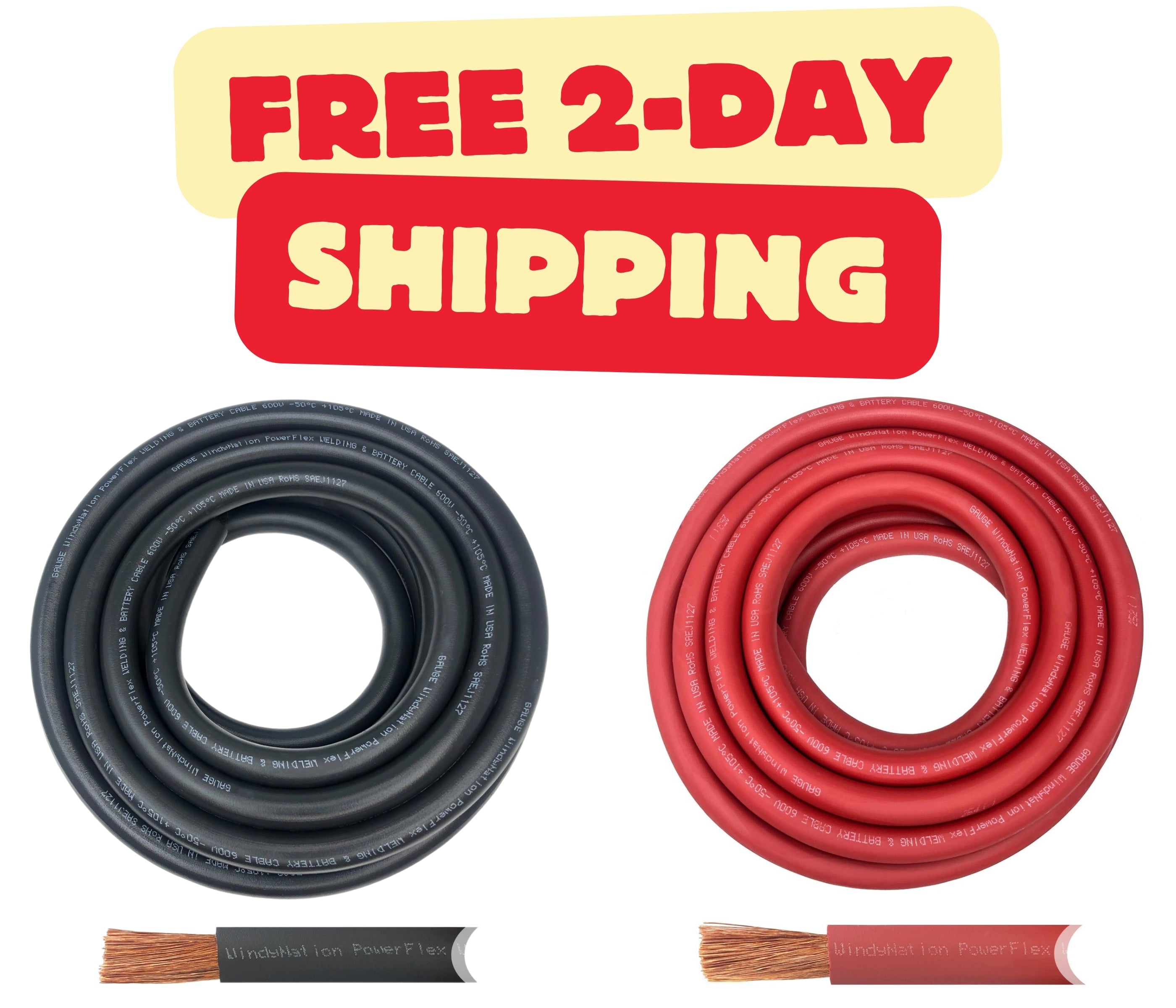
I'm not seeing the temp rating for the cable on the listing, can you screenshot it maybe I'm missing it. The one temp rating 125c looks to be for the shrink wrap.The wire I was planning on using is from Amazon seller recommeded by Will in his solar builds. Windynation. Shows its 105 rated.
2/0 Gauge 2/0 AWG 5 Feet Red + 5 Feet Black Welding Battery Pure Copper Flexible Cable + 10pcs of 3/8" Tinned Copper Cable Lug Terminal Connectors + 3 Feet Black Heat Shrink Tubing https://a.co/d/btTPjNm
Also 105c is very hot I don't like any of my wiring to be warm under normal conditions. When the wires are hot then it'll heat the bays then cause all kinds of issues.
 ;
;