diy solar

diy solar

Back feed for snow melting?

I haven't tried melting snow, but I have tried backfeeding PV panels.
Every cell is a diode, and it operates forward-biased, not reverse biased.
One illuminated PV panel connected in parallel with one side a dark room didn't drive enough current to do anything interesting.
With two panels wired 2S placed in full sun, paralleled with a single panel in dark room, the current flowing through the dark panel was about 0.4 x Isc. In the case of my 165W panels, about 2A at 41V or 82W dissipated.


If you have a power supply to deliver Voc to your array or to a string, at 40% of rated wattage, that could work. (may be a tall order)

We do have to stop and think whether portions of the array could be damaged, especially when parts of the array clear as described by Efficient, resulting in power and temperature not being evenly distributed.


Save soot and apply to face of panels with a blower (to more efficiently absorb light)?

View attachment 123815

This. We have a wood stove for all our winter heat. We spread the ash on the walkway to melt snow and ice.
 
I wonder if we will see combined PV/Solar hot water collection panels (Hydra-Solar) and if these would be more easily set up for snow melting; by running the hot water system to warm the panel enough to shed the snow. could be interesting.
 
Roof de-icing cable burns about 8 watts per foot. How much would the shading from the cable effect the panels performance?


Deicing_Heat_Cable.jpg
 
I think it is worth a try to use the PV cells for heating. Watts is watts, whether it is amps squared x heater element resistance or amps x forward voltage drop across a PV cell inherent body diode. Cannot get a better thermal bond then the actual PV cells to front panel glass.

A full thermodynamic analysis is a bit difficult due to all the possible variables, particularly panel backside heat loss but based on rear auto window defroster wattage it seems feasible. The inside of auto window likely has less heat loss particularly since interior cabin heating is usually on at the same time.

If a 3' tall x 6' long (18 sq ft) auto rear window has 100 watt heat strip then a 3.5' wide x 5.5' tall (19 sq ft) PV panel would need same ballpark. Maybe multiply by 1.5 to 2x the required power to account for backside loss and/or speeding up the process.

Now if you are trying to clear 20 panels at the same time, that sums to a bit of power, but not out of reality. All comes down to power x time and an empirical real-world experiment would be good way to find that out. Maybe do one series string at a time so you can use cleared strings to help produce the power to clear the remaining series strings.

If you just melt base against glass surface creating an avalanche that would greatly help shorten time, so panel tilt angle plays an important role. That may mean more heating for shorter period of time creates the avalanche quicker, netting less overall kWh's needed. You just have to play with amount of heating power to find the optimum.

Putting a temp sensor on backside of panel behind middle of one cell would give good info to make power push to panel adjustments.

Power source needs to be a current limited supply. Voc is 100% current going through PV cell inherent diode. Vmp is only about 5% going through PV cell inherent diode, so actual voltage will be between these two points. As cell heats up its forward diode voltage drop decreases so a fixed supply voltage would cause an increase in current which is why you need a controlled current source.
 
From my measurements, I think driving to about Voc is good, and will carry 40% of Isc.
I achieved that using 2s PV string in the sun paralleled with 1s PV panel in darkness.

Current limited sounds like a good idea. Slightly too high a voltage applied to forward biased diode (PV cell) could draw massive current.
Fuses for the string is a good backup, not sure that is sufficient to prevent damage (no fire is their job.)

How to do this is left as an exercise for the reader.
If able to freely rewire the array, would be easier. A boost converter may be the simplest retrofit.
 
I wonder if we will see combined PV/Solar hot water collection panels (Hydra-Solar)
I've been thinking about that, but not for snow melting. Running cold water through them will both heat up the water and cool down the panels. This would increase the power during the summer.
 
So I did a test today, totally overcast no incoming wattage on any of the arrarys. (ie all the arrarys show Voltage, but no watts)
outside temp -4 degrees C (25F) no wind, light snow this morning left 12mm 1/2" of snow on the panels. Panel is tilted 60-degrees from horizontal (30-degrees off of vertical)
My panels are Canadian Solar 440 bifacial half cut, Voc=48.7vDC, Isc=11.48
My bench source has max 40vDC 10 Amp output, so this is what I used.
I isolated one single panel, and connected the bench source.
The first 15minutes looked like nothing happening.
After half an hour, snow was visably melting around the panel edges (all edges top bottom both long sides) but nothing in the centre of the panel seemed to be happening.
At 1 hour the panel was half melted, mostly around the edges, with about 50% of the panel area centre still covered, but the melting water rivelts runninng down from higher up made the centre part all side at once at an hour and ten minutes. Using a laser temperature pointer does not work well on the reflective glass, but as best I could measure the glass was right at zero C /32F.
 
It is not obvious to me why perimeter would be effected more. Each series cell should be getting the same heating wattage.

Maybe the mounts, being bolted to the warmer roof, is providing some additional heat transfer from house into mount, then into edge of panels.

Placing temp sensors at a couple points on the panel may help explain this. Where it starts from and its progression.

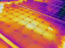
An IR camera would be great to examine what is happening.

Notice the frame perimeter in the picture.
1670767232849.png
 
Last edited:
Maybe the mounts, being bolted to the warmer roof, is providing some additional heat transfer from house into mount, then into edge of panels.
The panels are on my workshop steel roofing on steel building, the mounting system is galv unistrut raised up 12" above the roof at the eave (the pivot edge), and tilted 60 degrees at this time of year, the upper edge of the panel is 6 feet above the metal roof. The roof itself has about 6 inches of snow on it. I can garantee there is no heat transfer to the PV by the building/roof/racking at the moment.
I wonder if the edges melted first just because the heat applied is being absorbed more in the centre, whereas the perimeter - without any wind - has no where to go, but to melt the snow. It may be related to the half-cut line, in the middle where there is less concentration of PV cells in this area.
 
Gardening hose with warm water?

There are protective diodes that will bypass the panel if there is current in the forward direction. And the cells themself act as a diode in the other direction. So if you apply forward current - it will bypass the panel and if you apply reverse - it will not flow.

With proper installation, snow should not be an issue. If it is an issue for you it is likely that your panels are a bit too horizontal.
That is incorrect.

The normal output voltage when the panel is illuminated is such a polarity that would forward bias the cell.

If you apply a higher voltage than the normal PVmax in the same polarity as normal operation current will flow into the panel and the cells will heat up. I don't know if I would recommend it though.

The protective diodes are reverse biased in normal operation (and if you backfeed the panel). They conduct when the voltage across the panel reverses as would happen if the panel is shaded when in a series string with other lit panels. Most panels are divided into three sections, each with its own diode.

kevin
 
If you apply a higher voltage than the normal PVmax in the same polarity as normal operation current will flow into the panel and the cells will heat up
My bench source is max 40vDC, but the panel I am testing this on has Voc 48.7vDC; does this mean the actual current flowing will be far less than 10A? - I didn't consider measuring actual current, I just set the bench source to max which is 10A, as I was expecting it would just max out the current.
-now this is going to be on my mind all day unless I set this test up again, and this time measure the actual current flow.
 
Yes, far less. I got 41V at 2A backfeeding a 43Voc 5.5A Isc panel.

If you have a CV/CC supply and gradually turn up current limit you can observe current vs. voltage.
It is probably best to keep current limit no higher than Isc and voltage limit no higher than Voc.
 
My bench source is max 40vDC, but the panel I am testing this on has Voc 48.7vDC; does this mean the actual current flowing will be far less than 10A? - I didn't consider measuring actual current, I just set the bench source to max which is 10A, as I was expecting it would just max out the current.
-now this is going to be on my mind all day unless I set this test up again, and this time measure the actual current flow.
If you don't get above Vmp you won't push much current into panel.

At or above Voc, 100% of normal illumination current will go into PV inherent diode.

At Vmp, only a small amount of current will go into PV inherent diode. About 5% of amount at Voc.

Both Voc and Vmp change with temperature, about -0.34% per degree C. Current will increase, cell voltage will go down, as cell warms up.
 
Last edited:
If you don't get above Vmp you won't push much current into panel.

At or above Voc, 100% of normal illumination current will go into PV inherent diode.

At Vmp, only a small amount of current will go into PV inherent diode. About 5% of amount at Voc.

Both Voc and Vmp change with temperature, about -0.34% per degree C. Current will increase, cell voltage will go down, as cell warms up.
Today I set this test up again, yes, at 40vDC there is nearly zero Amp - measured with an accurate meter 0.2 Amps, no wonder it took over an hour to clear one panel. So I swapped the bench source with a higher voltage unit, this one can go to 60vDC, but only 5Amps. Accounting for the temperature Delta, I calculated the Max Voc to be 54vDC, so set the bench source to this, and max Amps (5A) and connected it up, the panel drew 5.1A, this warms the panel much faster.
But to set this up 'full scale' on a 2S-3P arrary I would need a controlled power source capable to deliver 108vDC, 30A - I would have to build something to do this, I don't have any DC sources higher than 60vDC, -LiFePO4 batteries 34S? (series connect two 17S)
Meanwhile, playing with a single panel is one thing, risking six panels, not so sure about doing that!
 
Notice the frame perimeter in the picture.

Different materials have different emissivity. The IR camera measures the emitted IR radiation.

Let me give an example. The numbers are most likely wrong, but let's say that we have aluminum with an emissivity of 60% and the panel part covered with glass has an emissivity of 40% and both are at the same temperature. In that case, the IR camera will show the aluminum part hotter than the glass part.

Measure polished stainless steel cup with boiling water. Last time if I recall correctly the IR thermometer was showing ~40C. But touching it was impossible.
 
Back
Top