Quattrohead
Solar Wizard
Certifications and full grid interaction. It is also very well builtWhat makes the EG4 18KPV worth twice as much?
Certifications and full grid interaction. It is also very well builtWhat makes the EG4 18KPV worth twice as much?
It does, PV and battery..... although I wouldn't recommend itDon't know if the unit has reverse polarity protection.
Yeah, they’re the proper positive/negative, and there was one plugged into mppt 1. Good thinking though.OTOH, None of this looks correct based on the manual. Then again maybe red is (-) who knows? This should probably be in it's own thread as well. "General" 18KPV should be stuff like firmware updates, strange behaviors in edge cases, limits/manual errata and questions. At a glance this looks to be generally wired wrong, and the picture does not show the wires in MPPT1.
View attachment 209249
View attachment 209250
Don't forget the overhead costs, paying EG4, Lux Power, Signature Solar employees etc.Certifications and full grid interaction. It is also very well built
I don’t mind paying off the NRE, testing, certifications, software development, customer service, support, etc (and funding them ongoing) as long as the reliability is there (which it appears to be or there would be lots of failures).Don't forget the overhead costs, paying EG4, Lux Power, Signature Solar employees etc.
Lol..does mean sol-ark must have a HUGE overheadDon't forget the overhead costs, paying EG4, Lux Power, Signature Solar employees etc.
So you have red as (-)? That is not a very good idea IMNSHO.Yeah, they’re the proper positive/negative, and there was one plugged into mppt 1. Good thinking though.
Indeed. YOU may know TODAY what it means but you’ve just laid a trap for someone (maybe yourself) in the futureSo you have red as (-)? That is not a very good idea IMNSHO.

I just plugged in my 3rd array to MPPT 3, changed the settings to 'MPPT 1, 2, 3 independently', and now no voltage is showing up in MPPT 1 even though I'm showing 430 volts in the terminal. Any ideas?
View attachment 209163
View attachment 209164
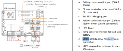
I'm using 'G', I think it's 19200, . . .So how many RS-485 interfaces are there on an 18Kpv and what are they used for? I'd like to talk Modbus to one of a pair of parallel inverters, and I'm still trying to wrap my head around the interfaces.
It looks like the parallel communications uses CAN bus, as does the battery communications.
From the manual:
/*
8.2 Third-Party RS485 Communication
Meters 485B and 485A can be used when a meter is not connected. These two pins can be used to com-municate with the inverter using the RS485 Modbus protocol.
INV485: This interface is shared with the Wi-Fi module. If the Wi-Fi module is not in use, this interface can be used to communicate with the inverter.
*/
View attachment 209415
Has anyone used the Meter 485 interface, and does it work as a Modbus slave as expected?
Thanks!
Good to know, thanks! Is it possible you are colliding with another master on that bus? I figured worst case I could use something like https://github.com/snhobbs/ModbusSniffer (I've used PyModBus on RPi before and it seems solid) to eavesdrop on the conversation between the LAN or WiFi dongle and the inverter, but I'm still noodling around with the best way to capture everything.[keith@powercontrol] /home/keith/SolarProject/panelmonitor<312>grep bus2 *.c
mb485_poll_id.c: s1812 = mb485_poll_1812(g.p485_bus2,sp);
panelmonitor.c: g.p485_bus2 = mb485_create(g.device_19200,19200);
I'm polling every 20 or 30 seconds. The polling is not super robust. It fails in various ways not in-frequently. I have the inverters set to ID's 6 and 7 (from the display). If any of the data looks hokey I toss the poll. I only have the two inverters on the RS-485 bus. Cable is short. You will notice I open/close on every poll. If I don't it's not reliable. Python code may be more stable, was going to write php library, but I just ran with C.
#define RESP_OFFSET 15
#define REGISTER_COUNT 20
//----------------------------------------------------------------------
// MB485_POLL_1812
// Read status from the inverter
//----------------------------------------------------------------------
STATUS_1812 *mb485_poll_1812(modbus_t *p485, SENSOR *sp) {
int x,ix,address,a;
uint16_t *value;
union {
struct mb_1812request r;
uint8_t rsp[MODBUS_MAX_ADU_LENGTH];
} u;
static union {
STATUS_1812 r;
uint8_t ov[160];
} v;
if(g.verbose) {
log_print(g.log,0,"Reading Inverter\n");
}
memset(v.ov,0,160);
memcpy(&(sp->s1812),&v.r,sizeof(STATUS_1812));
for(address = 0; address < 150; address += REGISTER_COUNT) {
memset(u.rsp,0,MODBUS_MAX_ADU_LENGTH);
u.r.device = sp->sensor_id;
u.r.function = 0x04;
u.r.address = address;
u.r.count = REGISTER_COUNT;
// fprintf(stderr,"Command:\n");
// mbdump(u.rsp,sizeof(u.r));
x = mb485_open(p485,u.r.device);
I only poll 20 registers at a time, 40 is supposedly the limit. I map the return values into a structure/union, one inverter right after another. I record the poll start time as the time for both polls but in can take a few seconds to get the poll completed.
I poll the 9600 bus for my sensors (7), with no difficulty. It did not work well sharing the bus with the 19200 poll. It's supposed to work, but it doesn't.
Good to know, thanks! Is it possible you are colliding with another master on that bus? I figured worst case I could use something like https://github.com/snhobbs/ModbusSniffer (I've used PyModBus on RPi before and it seems solid) to eavesdrop on the conversation between the LAN or WiFi dongle and the inverter, but I'm still noodling around with the best way to capture everything.
The pv input doesn’t have reverse polarity protection. It will burn the mppt board.As Ksmithaz has pointed out, you almost certainly have your polarities transposed. Don't know if the unit has reverse polarity protection.
double check your wire polarity with the multimeter and then switch either one of the mppt (2 or 3).I just plugged in my 3rd array to MPPT 3, changed the settings to 'MPPT 1, 2, 3 independently', and now no voltage is showing up in MPPT 1 even though I'm showing 430 volts in the terminal. Any ideas?
View attachment 209163
View attachment 209164
Anyone know what the latest LCD version is?


