Murphyslaww
New Member
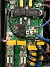
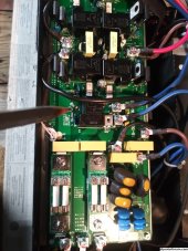
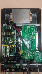
Connected the refurb 6000ex AIO I got from Signature Solar, and output L1 to ground is 109v, and L2 to ground is 131v. What would cause that?
I’m assuming it needs to go back. Wonder if that was the original problem as the system looks like it was dropped or something.
I’m assuming it needs to go back. Wonder if that was the original problem as the system looks like it was dropped or something.