diy solar

diy solar

New no battery pure sine wave solar power system with smart switchers.

Testing ended early, under small loads inverter output AC voltage climbed to above 250VAC from 50% duty cycle solar panel capacitor charging.

Also lost N channel output, obviously more work ahead.

Recommend project system, all the bugs have already been worked out,

Best wishes
 
First will restore N channel operation on the two FET inverter get it ready for more bench testing, must understand why the inverter AC output voltage spiked, went north of 250 volts just as N channel stopped working.

All solar inputs less than 181VDC, Diodes were installed to capture the spikes from 50% duty cycle points to a few less solar panels needed and other adjustments.

Good news it responds OK to high voltage, Bad news is the voltage turbo boost I built blew up the engine and I don't immediately have a good solution to fix this.

This thing makes big energy and voltage, P channel servives no matter what, bought 2 P channel Mosfets at $20 each and both are running like new, amazing.

Just a matter of time to tame this wildcat inverter.

Back on the work bench and with a slight increase on the LED drive for the N channel it is back working again, Inverter servives first encounter with actual solar panels.
All in all a successful test bulb was burning brightly when N channel stopped, once I noticed the voltage spike the power was pulled.

Best wishes
 
Last edited:
Long term plans use another 12VDC floating power supply circuit for the 555timer power, Add a simple transistor circuit to get the logic correct on the 555timer for inverter dual 60Hz signal.

Excited at the progress today.

Testing pushing larger loads like fan motor, saws all, big soldering iron once I get the output voltage to the correct level it should work nicely, Think before next solar panels test I will bypass the input diodes that trap energy/voltage.
This may in time become a automatic voltage boost when the inverter needs it most.

Good preliminary results fan spinning even on the lowest setting, soldering iron got hot.

Calculations show I need a lower solar panel input voltage between 130volts and 140VDC for B1 and B2 sources.

This will require some roof top work have to drop two panels each on each array and disconnect a third array to get a balance test condition.

More soon
 
Last edited:
Doing calculations aiming for 1400 watt minimum system using 14 standard 12VDC solar panels 28 panels gets 2800 watts approximately.😀

Think it is interesting 9+9+9 =27 panels for the full project system 15amps the new two FET inverter needs (7+7)=14 B1 and (7+7)=14 B2 for a total of 28 panels to make the full system.

More testing required.

More soon
 
Last edited:
Bad solar day probability won't sun test until conditions improve added additional input wires that bypass the capture diodes on the inverter. New input leads are fused at 5amps after full testing the fuses will be increased to 10Amps.

Last night did more motor push test seems on track for a win but looking forward to full sun testing, will need to reconfigure the roof top solar for proper testing. It all looks good but the 60Hz signal from grid sine wave is narrow/skinny the signal from the 555timer is alot wider and will naturally push a motor/heater better.

Diagram of current input/output main power flow and target voltage. Target 15Amp 28 standard 12VDC solar panels. Very simple design.

(Just figured out today the forth, 140 VDC for B1 and B2 is perfect for 220VAC inverter output 60Hz or 50Hz) not yet found the best input voltage for 120VAC output.

The above statement is wrong it will likely take B1 14panels and B2 14panels minimum to provide 220VAC 50Hz/60Hz power.

More soon 😀
 

Attachments

  • 20240401_105217~2.jpg
    20240401_105217~2.jpg
    97.2 KB · Views: 14
Last edited:
Weather is not cooperating but my newest plan is to build two mc4 extension cords that will bypass two solar panels each out of wire and connectors I already have.

During the previous live test inverter demonstration it servived an overvolt situation, this time looking for steady operations for long term power production and testing.

More soon
 
Roof top solar panels have been reconfigured for the two FET inverter, The minimum panels 7 (B1) + 7 (B2) 1,400 watt configuration 14 standard 12VDC solar panels, Has been voltage tested but may take a short while till I am ready to start inverter testing.

Need more sun 🌞

More soon
 
Wish I had better news to report with B1&B2 voltage at 140VDC was getting 200volt AC output from the inverter?

Light bulbs burned very bright and steady but once I tried a motor it started immediately with a slight hum and inverter failed seconds later with what I suspect was the N FET going shorted.

Test generating more questions than answers, have parts to restore operation but changes are definitely needed.

Suspect I am overdriveing the opto couplers/FETs, will repair and readjust drivers and test again, will do more voltage testing before reducing the number of solar panels.

More soon
 
Last edited:
As suspected the N channel FET 40N65 failed shorted source to drain, have been playing with P channel looking this time for the lower dive limits.

40N65 FET replacement in progress, Takes a serious amount of energy to trash that peticular Mosfet, bad news today but good news down the road.

More information in previous posts.

More soon

40N65 FET replacement and basic operation restored, 100K potentiometer for the P channel opto LED brightness is perfect 500K potentiometer on N channel does not work correctly don't care if it is just a single resistor got to get the brightness down and the system voltage down.
 
Last edited:
Drivers adjustment completed, ready for tomorrow, each optical coupler is set one notch above what it takes to glow the bulb element, when both P & N channels are powered 21VDC it gets more than twice as bright.

Now that the solar panels are near the correct voltage fast forward progress is expected, right now need the two FET inverter to demonstrate better voltage regulation/control, need to get control of this wildcat inverter.

More tomorrow, Full sun expected Monday and Tuesday coming week.

More soon
 
Last edited:
Wow both B1 & B2 at 140VDC 7 panels each with the FET gates running on a low setting 60Hz timing, Output from the inverter is at 220VAC. I have a stable situation running light bulb on a serious overcast day. For those looking for 220Volt 50Hz or 60Hz power here is your exit ramp.💚

My plan is to reduce the input voltage on both B1 & B2 till 120VAC output is achieved, after that hopefully full sun and full testing ahead.

Will back fill with solar panels for more amps once the input voltage mystery is solved.

Have a nice setup for continuing to test the two FET inverter during day time hours just a matter of time till I dial in the right settings, it was a small setback when the 40N65 MOSFET shorted but it was also a big tell about what is going on inside that inverter once I adjust the drive correctly the energy that caused the shorted FET will come out of the inverters output as 120VAC goodness.
Just a short time till I get it.

Has been running for hours now in the 220Volt mode, minimal loads, target 120VAC before I start load testing, hope you understand.

Current calculations suggest 4 panels each B1 & B2 for 85 volts 800 watts that still may be a notch high but the inverter will have the advantage 170 volt DC total input.

Something unexpected looking at 80 VDC or less main input voltage X 2 going forward instead of 180VDC, things like that make me happy 😊

The original circuit diagrams for the solar panels layout has to be wrong way too many panels, I will supply correct information later.
Best wishes
 

Attachments

  • 20240404_133317~2.jpg
    20240404_133317~2.jpg
    242.8 KB · Views: 2
  • 20240404_133307~2.jpg
    20240404_133307~2.jpg
    115.4 KB · Views: 2
Last edited:
Shutdown on the new inverter for the night with 50 watt load running for hours the FETs heat sink was cold to the touch.

Disconnected the solar panel inputs watched bulb dim out to zero and unplugged to 60Hz signal for a safe shutdown.

Tomorrow disconnect three panels each from B1 & B2 and retest everything again, looking forward to full sun now that we are looking at lower input voltage.

Another few steps forward today, increasing stability, and a hint that a optic coupler settings lower than what it takes to glow the bulb in the 21VDC test may be the perfect inverter setting at full voltage.

More soon
 
Last edited:
Good morning, B1 & B2 power power sources are at solar 80VDC, heavy overcast sky waiting for full sun, currently the new two FET inverter is running smooth with a 25 watt bulb load and 115VAC 60Hz output. Here is your exit ramp for 120VAC 60Hz or 50Hz power production with the new two FET inverter.❤️

Initial perfect performance, B1 with 4 standard 12VDC solar panels and B2 the same 800watts if you (4+4) on each input keeping the same 80VDC you can get 1,600 watts approximately.

Load testing will progress slowly today💚

First load test added 30 watt soldering iron to 25 watt light bulb, Mixed results unacceptable voltage drop to 98VAC but the lamp and soldering iron working just fine, suggesting higher optic drive output adjustment is needed. This will be a slow process to increase the inverter output amps but I am up to the challenge.😀
More information soon
 

Attachments

  • 20240405_104027.jpg
    20240405_104027.jpg
    145.3 KB · Views: 2
  • 20240405_104049.jpg
    20240405_104049.jpg
    181.6 KB · Views: 2
Last edited:
As it stands right now the inverter can run 6 of the 9 watt LED bulbs 60watt equivalent, during this test I disconnect all loads except the voltage meter the voltage spiked and the N channel FET went shorted source to drain.

Although the N channel failed shorted once I disconnected the input power source for the N channel the active P channel relit the bulbs, P channel FET servives everything every time.❤️

P channel FET is the largest physical size I have ever owned and seems immune to abuse, Need to aquire a N channel FET that is its equal in every way for the big win!

Several changes are needed here, more later. Two steps forward and one step back.

Taking a moment to mark the progress here took a fantasy drawing of a two MOSFET inverter and as of today we are starting to run things long-term lights/ heat, many more adjustments needed
to get full power.
 
Last edited:
Getting ready to install the third good used 40N65 MOSFET on the two FET inverter to restore operation, not sure the direction to take next to increase amperage but small steps will show the correct way/direction.

Was seconds away from showing you multiple LED bulbs burning brightly when the N channel went down.

More soon
 
Inverter restored, as an experiment going to test the lowest possible inputs on the optic couplers, seriously don't think this is the direction needed but new project needs the data, will also test the setting slightly higher than the previous testing looking for a boost.

Bench testing and preparation for tomorrow, unexpected voltage surges need to be solved.

More soon
 
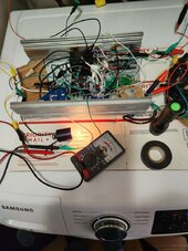
Good morning up early, I will post today's updates on this post check back several times. First thing in past testing when the optic drivers were tuned much higher I was getting alot more than 55 watts of energy. It is going to come down to one of three things.

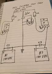
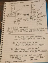
1. Need much lower optic coupler settings and higher voltage from the solar panels B1 & B2, prepared to test this currently at 80VDC and can go up 20VDC at a time to 180VDC.

2. Need a higher optic coupler output settings than previous test but less than full. Prepared to test as well.

3. Not driving the gate FETs correctly, With the correct FETs, driver and DC input voltage with baby step testing I should find the the output these Mosfets are rated for.

Proceeding slowly have discovered a long range of optic coupler settings well below what it takes to glow the bulb in the 21VDC bench testing, may have discovered the voltage control I have been looking for if this is the correct path soon will be uping the voltage from the solar panels.

Have finally found voltage control for the two FET inverter AC output! This will pay off big time in the long term have lowered output voltage from 115VAC to 60VAC, Unfortunately will need to reconnect the panels I disconnected a few days ago to get it back up to 120VAC.

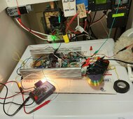
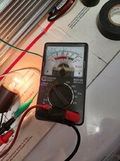
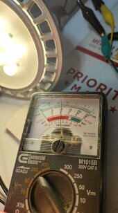
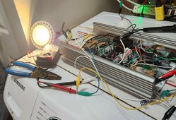
Great news just passed 225 watt load test and the inverter is still running, 115volts AC output 60Hz with solar input 140VDC for B1 & B2, output voltage much more steady. Pushed small Honeywell space heater and LED spot light working smoothly.💚

Secret is a very low optic coupler setting and higher input solar panel voltage got it right the first time for 120VAC 140VDC input, 220Volt will require more panels, have improved operations by small increase in LED brightness on both channels, hope to nail it all down soon with diagrams and correct parts list.

100K potentiometers on the optic couplers work perfectly once you look for and voltage test the FET output voltage you get perfect control, Works great but needs more fine tuning, was going to double check the flyback diodes on the FETs to see if they were causing any issues but as of right now it is full steam ahead 😀

Taking a break now.
😀
 

Attachments

  • 20240406_123048~2.jpg
    20240406_123048~2.jpg
    99.3 KB · Views: 6
  • 20240406_123037~2.jpg
    20240406_123037~2.jpg
    326.6 KB · Views: 1
Last edited:
Big success today, check previous post.

For tomorrow going to beef up all main DC inputs and try again, was making live adjustments on the inverter and found a sweet spot just before ending testing for the day, could really use a second 100K potentiometer.

Winning this 💚
 
Last edited:
Detail diagram of what I have working with the FET numbers with part values and optocouple setup instructions.

Small changes expected as we go forward, more testing tomorrow.

Current look at the stereo output , The upper and lower spikes are from the 50% duty cycle voltage spikes, still working on capturing and turning it into more energy. Just need to level it off or sloped slightly.

More soon
 

Attachments

  • 20240406_192747~2.jpg
    20240406_192747~2.jpg
    157.3 KB · Views: 8
  • 20240406_181149~2.jpg
    20240406_181149~2.jpg
    287.5 KB · Views: 2
Last edited:
Back
Top