diy solar

diy solar

New no battery pure sine wave solar power system with smart switchers.

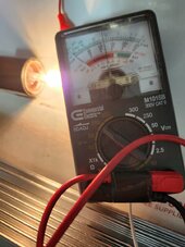
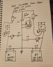
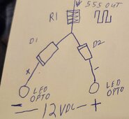
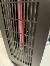
520 watts continuous output from the new two FET inverter running space heater on first stage and light bulb. 100 volts 60Hz fan motor runs smoothly heater is providing good output.

Success ❤️

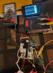
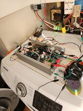
Running great considering it is all on alligator clip jumpers.

Sure to make more improvements, solved many mysteries in the past few days concerning driving the FETs. Loving it!

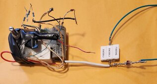
Ventilator fan for the two FET inverter heat sink is now 24/7 powered, soldered and insulated many inverter connections.

Nice way to start a day, more later 😀
 

Attachments

  • 20240407_091610.jpg
    20240407_091610.jpg
    152 KB · Views: 6
  • 20240407_091553.jpg
    20240407_091553.jpg
    175.2 KB · Views: 7
Last edited:
B1 seven solar panels 140VDC.
B2 seven solar panels 140VDC.
60Hz signal derived from two small grid powered transformers work on the 555timer will continue soon.

Low load on the inverter 125VAC, warning right now no load causes issues with the stability of the inverter, another thing to work on.
Recommendation use 25 watt standard bulb minimum till I fix this. Not tested yet but inverter direct connection to an ISO transformer may automatically cure several current issues no load, spikes in sinewave, rounding the sine wave, and most important of all when this thing has a FET fail fault it channels DC voltage directly to the output only way to properly protect you and your equipment is to use an isolation transformer (ISO)⚠️
DC can not pass through a AC transformer especially an ISO transformer.

Best wishes 💚
 
Last edited:
First bad news new inverter pushes wound AC motors OK but brush motors like a vacuum cleaner or saws all is a big No.

Shorted out both FETs, Yes I finally killed the P channel FET, fortunately I have backups, also going to order more FETs now that I have a clue what I need.

Don't like killing parts but also need to know this stuff to make forward progress.

More later.
 
Ordered more (5) 40N65 MOSFETs N channel and a different part # P channel Mosfet rated for 200Volts 11amps getting ten of them.

Since I just stole the P channel FET from the test card board based inverter it will be rebuilt with cheaper parts it will be eventually tested with earth ground and is not expected to survive.

I see nothing but good to coming from the past three days of testing the new two FET inverter.

More soon 😀
 
Double FET replacement and the inverter is back 100% operational.

Exact Mosfets as before, Both P and N channel FETs were shorted source to drain, how it did not blow a 5amp fast blow glass fuse on either side whilst it cooked a 20amp N channel FET and 40amp P channel Mosfet blows my mind.

If it wasn't amps it must have been a voltage spike in excess of 500 volts!

Best wishes More tomorrow
 
Last edited:
Had a brain storm, hope it works, based on today's testing the lower the optic couplers and the higher B1 & B2 voltage the more amps output you get.(Over 500 watts currently)

Instead of 140VDC for B1 & B2 if I raise the input voltage back to the original 180VDC and tune the optic couplers back down to 120VAC output guess what's going to happen with the output amperage?

Bet it increases, all that energy that has been killing the FET parts will go to the output.

Tomorrow promises to be exciting, Success with this will put the Project system and the new 2 FET inverter on the same platform 😀
 
Last edited:
Starting today with a new optic coupler settings, on a 21VDC bench test.
5VDC on B1 inverter output only.
-5VDC on B2 inverter output only.
Check: B1 on B2 on inverter output is 9 to 10 VAC. Standard 25watt 120VAC bulb for load.

Both B1 and B2 solar panel arrays will be put back to the original 180VDC configuration.

Wish me luck, Slow testing ahead, Hope to have a working two FET inverter at the end of this day.

More soon 😀
 
Last edited:
Starting today with a new optic coupler settings, on a 21VDC bench test.
5VDC on B1 inverter output only.
-5VDC on B2 inverter output only.
Check: B1 on B2 on inverter output is 9 to 10 VAC.

Both B1 and B2 solar panel arrays will be put back to the original 180VDC configuration.

Wish me luck, Slow testing ahead, Hope to have a working two FET inverter at the end of this day.

More soon 😀
Be careful when you get on the roof to reconnect those panels!
 
Be careful when you get on the roof to reconnect those panels!
Down from the roof due to rain, my B2 is back to 180VDC, B1 is not working and I opened several connections till I can figure out why the problem exists.

Two FET inverter adjusted and ready for testing, just have to fix B1 DC supply, game called due to rain.

Have a chance to put the third set of 9 panels180VDC on its own set of conductors for the new systems.

More soon
 
Last edited:
Both B1 & B2 are at 180VDC, Two FET inverter output 120VAC 60Hz.💚

Have full control ❤️ but 100K potentiometer adjustment is touchy.
Bet a 50K potentiometer would work better operating near one end.

It is working but raining outside so I am going to wait for more sun to load test the inverter, everything looks good right now.

Think I can now connect the input diodes for more energy. Feels nice to actually have adjustable voltage control.

Both the new two FET inverter and the Project system share the same 9 standard 12VDC solar panels 180VDC input. All I have to do is connect one solar input wire together and I am ready for summer and testing the heck out of this inverter.


It really works 😍
 

Attachments

  • 20240408_125614.jpg
    20240408_125614.jpg
    119.7 KB · Views: 2
Last edited:
Just figured out passing the full inverter input through a pair of diodes to collect the voltage spikes is a bad approach, instantly putting the direct inputs back the way they were, any spike modifications will have to be done down stream of the main.

Still making progress on all fronts just a short time till I lock in on the best configuration for power production.

Going to call it a day, raining outside
 
Last edited:
Came up with a idea to filter/change the spikes while not interfering with the main power flow. Picture

Just a little more testing, already had it running smoothly enough at 140VDC to convince me. Just need to move the two diodes I currently have to make this work.

This is going to be great!

More soon
 

Attachments

  • 20240408_195828~2.jpg
    20240408_195828~2.jpg
    127.7 KB · Views: 7
Last edited:
Today it is expected to rain all day, Going to work on other things till the sun shine returns, once I get the inverter running again at more than 500 watts it will be tested with the 10amp ISO output transformer, I have a feeling that many of the current stability issues will dissappear once the inverter output is run through the transformer.

Working to bring the third set of 9 panels 180 volts DC down on it's own wire to the inverters.

I have been warned to stay on subject but my EV car solar charging is a big part of this unique power project, Car has been at the dealership since before Thanksgiving waiting for a new main high voltage battery related to a national recall on about 2,000 cars, Was told late December the battery was on US soil and under going customs inspection.

About two weeks ago I was informed by the dealership the battery is back ordered with no additional information,
They are only offering $4,000-$5,000 in trade on a car that is waiting for a $20,000 battery plus I paid $24K for a car that only delivered 20,000 miles before it died on the side of the road, paying full insurance on the car, Just renewed the EV tag for another year $235, paid over $200 to have the car towed to the dealership, this is my wife's main car with no loaner because I didn't purchase the car at the place the repair is to take place, No one is doing anything to help us, Any advice?

If I knew then what I know now, My advice Don't buy an electric car.


More soon 😀
 
Last edited:
Always more going on behind the scenes than you can imagine, just put the two 180VDC feeds back on the Project power system and took it out of night mode where it has been for the past several days of operation.

Next is to hard wire the third 180VDC feed to the inverters in preparation for running the mini split air conditioner in summer,

I like being able to individually test each solar array if necessary, all three glass fused at 5amps.

Have not lost any solar panels due to using direct drive input but have one example of a blown 5 amp glass fuse off a 9 panel array.

More soon 😀
 
Last edited:
Expecting a few more days of rainy conditions so I will build another 12VDC floating power supply and attempt to move the 555timer 60Hz signal to on board inside the inverter.

Since the timer will be powered by the outside + & - feeds it will properly trigger both P and N FETs, I now know exactly what to look for in triggering the Mosfets. No additional transistor circuit to correct logic will be needed.
Also the better square wave of the 555 timer will push more energy/amps.

Best news is I will get my step down transformer back so the oscilloscope can analyze the full power sine wave.

More soon

Picture 555timer ready with 5VDC power supply for final bench testing and installation into two FET inverter.
 

Attachments

  • 20240410_143430~2.jpg
    20240410_143430~2.jpg
    270.5 KB · Views: 1
Last edited:
Actually installing 555timer assembly into inverter, changing 12VDC Zener diode to 5VDC Zener expect 5volt will help stabilize the timer, going to dismantle the two transformer 60Hz signal assembly and reuse the 100K potentiometer and two glass diodes to trigger the FETs.

Much bench testing ahead in preparation for another dual 180VDC solar test, have seen this inverter run smoothly during the 140VDC testing, with additional adjustments I know it will be a big power producer of green energy 💚
 
No luck with my 5.1 Zener diodes but the 12 volt zener is working just like the two previous power supplies for the FET gates. The max voltage for the 555timer is 18volts the 12VDC power feed seems very stable going forward with 12VDC.

Picture is proof of operation at 21VDC, Beautiful square wave from the 555 Timer. DC control at 12VDC.

Slow progress today but bet tomorrow the inverter will push more power with the internal 555 timer.

Second Picture figured out for real the logic needed to drive the optic coupler LEDs in stereo, Tested and works.

Another solid step forward.

More soon
 

Attachments

  • 20240410_183056~2.jpg
    20240410_183056~2.jpg
    142.3 KB · Views: 6
  • 20240410_201035~2.jpg
    20240410_201035~2.jpg
    109.6 KB · Views: 6
Last edited:
Currently making changes so I can dim the LEDs in the opto couplers properly, Know the exact limits and need this to be corrected the right way before the next voltage test.

Problem encountered when attempting to run both opto LEDs at the same time, a real head scratcher that must be solved before I can high voltage test again, they go full brightness and no signal once it touches the opposite side of the 12VDC power.

Looks like I need access to pin 4 of the 555timer to get rail road LED flashing lights.

More soon
 
Last edited:
Think all I need is VCC added to pin #4 for reset bias for pin #3 to drive the opposite LED, if I can expose pin 4 from the silicone caulk I will test it on the current circuit if not a new configuration and new 555timer will be needed.

Still in the game with the 555timer 😀
 
My first couple of attempts have failed to provide the necessary output on my dual trace scope, same exact problem as before that forced me into the grid powered small transformers for 60Hz signal.

Testing a new 555timer configuration attempted to add wires to the existing config and no joy, Simply does not work like the YT video examples.

Only difference this time is a YouTube video on transistor flip/flop and signal inverters, in another short time I will have it working properly 😀
 
Last edited:
Back
Top