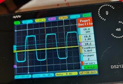
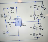
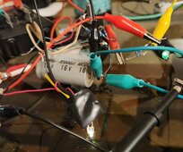
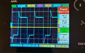
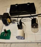
Built a simple but rare signal inverter, Guess what It works perfectly Transistor shorts out resistive circuit turning off the LEDs power, Stereo square wave output, Looking at FET trigger signals on the oscilloscope, already driving a set of LEDs like the optic couplers.
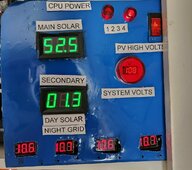
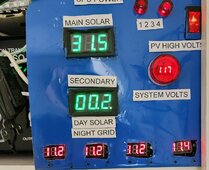
Definitely going to be one of a kind inverter, Just need to bring it all together for one more solar test, Smooth operation at dual 140VDC, Reaching a little higher next time testing with dual 180VDC looking for more inverter amps output.
Glad I already know how to set the FETs also have got lucky twice with manual live adjustment of the optic couplers brightness, let's just call it sweet spots or running real smooth.
The 555 timer and transistor signal inverter pulls less than 100 miliampers from the floating 12VDC power supply that is capable of 150 miliampers.
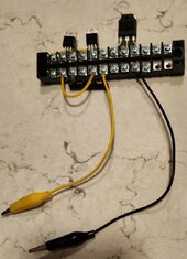
Second Picture: White and Green LEDs are dim on purpose, transmitting 58Hz stereo signals.
Solid step forward, need to power down the transistor circuit if the 555 timer goes off for any reason. Better than expected results square wave output looks nice on the oscilloscope.

Need good brightness control for both channels. Excellent results in pretesting, so very close now.


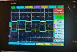

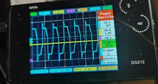
 So far only thing that has changed is the way I am driving the optic couplers, Looking more like a sinewave
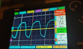
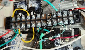
 once I turned up the N channel it was a short.